
Installation Guide

Continued
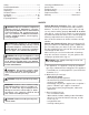
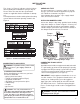
The charts in Figure 2 indicate technical inform-
ation regarding the installation of your gas log set.
Please make sure that all of the specifications
shown are applicable before installation is attempt-
ed.
The fireplace must include a working flue and venting
system with the minimum openings shown in the
Figure 2.
CHECK GAS TYPE
Use only natural gas. If your gas supply is not nat-
ural gas, you must convert the appliance to propane
/LP. Follow the instructions on page 7.
-
If the fireplace does not have a gas supply shutoff
valve, one must be installed.
INSTALLATION
Figure 2 - Technical Information Charts
BURNER ORIFICE
LOG
SIZE
NATURAL PROPANE/LP
In. Num. In.
FUEL PRESSURE
SPECIFICATIONS (W.C.)
Inlet Manifold*
NG 5.5"-10.5" 3.5"
LP 11"-13" 10"
* ± .2"
MINIMUM FIREBOX SIZE
LOG
SIZE
FRONT
WIDTH
BACK
WIDTH* DEPTH HEIGHT
MINIMUM
FLUE SIZE
8" dia.
18" 28
"
21" 15
1
/
2
"
16.5"
DESCRIPTION
Btu\Hr Input
Natural Gas
Btu\Hr Input
Propane Gas
50,000
18" Dual Burner 50,000
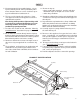
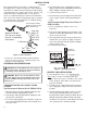
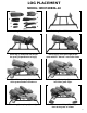
INSTALLING DAMPER CLAMP
Secure the damper stop clamp provided to the leading
edge of the damper as shown in Figure 3. If for any rea-
son this clamp doesn't work on your fireplace, another
suitable clamp or permanent stop must be installed, or
the damper blade must be cut or removed.
Damper
Damper
Clamp
Damper
Manufactured FireplaceMasonry Fireplace
Damper
Clamp
Damper
Figure 3 - Attaching Damper Clamp
CONNECTING TO GAS SUPPLY
WARNING: A qualified service person must
local codes.
connect log set to gas supply. Follow all
Installation Items Needed
Before installing log set, make sure you have
the items listed below.
• piping (check local codes)
• sealant (resistant to propane/LP gas)
•
equipment shutoff valve
• adjustable (crescent) wrench or pliers
• sediment trap
• tee joint
• pipe wrench
CAUTION: Use only new, black iron or
steel pipe. Internally-tinned copper tubing may
be used in certain areas. Check your local
codes. Use pipe of 1/2" diameter or greater to
allow proper gas volume to log set. If pipe is too
small, undue loss of
volume will occur.
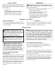
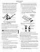
Installation must include an equipment shutoff valve with
"T" style handle, gas union and, for propane/LP gas only,
a plugged 1/8" NPT pressure tap. Locate NPT tap within
reach for test gauge hook up. NPT tap must be up-
from log appliance (see Figure 4).
CONNECTING TO GAS SUPPLY
Continued
IMPORTANT: Install equipment shutoff valve in an ac-
cessible location. The equipment shutoff valve is for
turning on or shutting off the gas to the appliance.
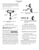
Apply pipe joint sealant lightly to male NPT threads.
This will prevent excess sealant from going into pipe.
Excess sealant in pipe could result in a clogged burner
WARNING: Use pipe joint sealant that is resistant
to liquid petroleum (LP) gas.
5
18” .144 #27 .079” #47
Num.
8" dia.
24" 32
"
24" 15
/
2
"
18"
60,000
24" Dual Burner 60,000
60,000
30" Dual Burner 60,000
24" Dual Burner
8" dia.
30"
36
"
28" 15
/
2
"
20"
24” .173 #17 .089” #43
30” .173 #17 .089” #43
injector
stream