
User manual

www.emaxmodel.com
SKYLINE32
4
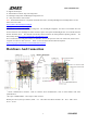
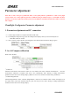
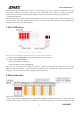
⑨Micro-USB port: For firmware upgrade and configuration.
⑩FSY connector: FrSky output,Connect this connector with RDX in FrSky receiver telemetry port
⑪Status LED(Green)
⑫Mode LED (Red): The LED will be on for the corresponding mode chosen.
⑬Power LED (Blue): LED on when the board is power on.
⑭OSD Module power indicator(Blue) .Note: Only SKYline32+OSD Version
⑮OSD module serial port: this is used to update the firmware and interface setting for OSD module.
Note: Only SKYline32+OSD .Because USB and OSD sharing this port,so please turn off the OSD when updating the
FC firmware and OSD firmware.(Switch OSD power to OFF),avoid any conflict that caused by using FC and OSD,FC
and USB meanwhile that couldn’t connected with computer.
⑯ OSD module status indicator. It can be judged by the indicator whether OSD module is under working condition.
Note: Only SKYline32 + OSD version.
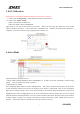
[A] 3.3V voltage-resistant GPIO port, this pad connected with the STM32 PB5 pin. This pad can not be connected to
5V voltage, otherwise it will burn the device.
[B] 5V voltage-resistant GPIO port, this pad connected to the STM32 PA15 pin . Can be connected to the IO port of
5V.
[C] 5V expansion pads. This pad,RC input interface and 5V power with the same source,convenient to power other 5V
outer equipment up.
[D] 3.3V expansion pad. This pad supply power for equipment with low power, such as Spektrum satellite receiver or
Bluetooth module.
[E] Ground pad. When using 5V or 3.3V power supply to power outer equipment up, connect this pad could enable
outer equipment and flight control system with common ground.
[F] 3.3V ADC input pads. This pad is connected to the STM32 PA5 (ADC12_IN5), access to pad as the signal strength .
Note: This pad only limited within 3.3V pressure, couldn’t be connected with 5V.press.
[G]OSD power switch. Note: Only for SKYline32 + OSD version.
As USB and serial OSD share the serial port, so please switch it to OFF when update the firmware of flight control and
OSD , to avoid serial ports conflicts when use flight control and OSD simultaneously, so that causeflight control and
USB can not connected with computer.
[H]OSD module connected to peripheral input / output pads. BAT1 / BAT2 are two battery test pads, VideoIN
connected camera signal, VideoOUT is connected with camera signal, RSSI is detection pad of signal strength , CURR
detection pad of current. NOTE: Only SKYline32 + OSD version valid. Camera, FPV and flight control must share
GND,which can be connected to soldering panel of the flight control.
[I] OSD module ISP communication pad used for download of OSD module boot code .
Note: Only SKYline32 + OSD version valid.
[K]RGB light pads. DI pads connected with CH5, can be used as RGB input.
Caution: Please note that all the wires connecting direction of wiring, if reversed that may burn flight control board
or external device for access.
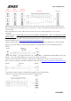
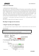
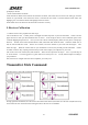
Motor Connection
Figures below show motor position and rotation: