
User manual

www.emaxmodel.com
SKYLINE32
3
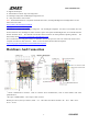
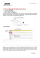
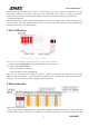
PPM GPS Standard
Connection Connection Connection 10Pin Wire RC_IN
When GPS feature is enabled, CH3 and CH4 are used for GPS connection.(CH3:TX, CH4:RX). When using PPM receiver,
these are normally unused, with standard receiver, connect AIL to 1, ELE to CH2, THR to CH5, RUD to CH6, and AUX1/2
to CH7 and CH8.
When using PPM receiver, CH5 to CH8 can also be used as motor or servo outputs, depending on frame type and
configuration.
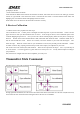
③Bootloader pads: ***ONLY USE IF GUI CAN NOT CONNECT TO SKYLINE32. This is not required for normal
firmware updates. When upgrading firmware, use tweezers to short pads together and power SKYLINE32 on by USB
cable. After power LED indicator turns blue, then remove the short. Firmware updated tool can then be used to reload
firmware.Download source: http://www.yinyanmodel.com/en/DownList.asp
④Battery Voltage Monitor: connect this header to battery or power distribution board to enable battery voltage monitoring.
Supports Up to 6S LiPo battery. No reverse polarity protection - connecting battery in reverse will instantly destroy the
hardware.
Power 2Pin Wire Vbat
⑤ESC / Servo Headers: From right to left: GND,+5V,PWM1- PWM6. Standard mode: PWM1-PWM6 for ESC input
M1-M6; Servo mode: PWM1-PWM6 for servo input S1, S2 and ESC input M1-M4.
⑥Buzzer: connect a buzzer here while battery voltage monitor is enabled, buzzer used for a low voltage alarm. Setting
battery voltage in Configuration of Parameter adjustment, kindly refer to :http://www.yinyanmodel.com/en/DownList.asp
Buzzer 2Pin wire Buzzer
⑦I2 Connector:Used for outer I2C communication equipment, such as OLED module.
⑧SWD port: for software modification during software development period.
5Pin wire SWD