
Use and Care Manual


EMAX
12 | P a g e
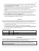
Piping (Safety steps)
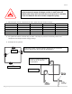
1. Install appropriate flow-limiting valves as necessary according to pipe size(s) used and run lengths.
This will reduce pressure in case of hose failure, per OSHA Standard 29 CFR 1926.302(b)(7).
2. Flow-limiting valve are listed by pipe size and rated CFM. Select appropriate valves according to
manufacturer’s recommendations.
3. Use a flexible connector between compressor tank and dryer/piping system to minimize noise,
vibration, pump wear, and to prevent damage to the unit or piping system.
4. Install ASME code safety valves and ensure piping system is equipped with adequate condensate
drains.
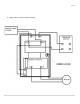
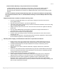
Typical stationary electric compressor set up.
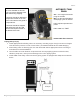
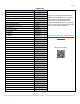
AUTOMATIC TANK
DRAIN
Sec. – the length of the drain/
purge in seconds.
Min.- set the interval between
drain/purge cycles in minutes
Drain requires separate 110v
power.
Drain outlet is ½” FNPT
Removeable filter clean out
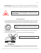
The automatic tank drain does
not come installed on this unit.
This is to prevent damage to the
tank drain during shipping.
Tank drain should be attached to
compressor located on the rear
of the unit under the belt guard in
a separate box.
Tank drain should be wrapped
with teflon tape prior to install
into the bell coupler located at
the bottom of the tank.