
Technical data

13
BASICS - Audio Filter
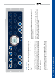
Audio Filter
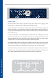
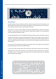
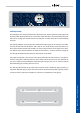
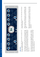
The Audio lter is placed behind the compressor, avoiding unwanted inuences on the detection
circuit of the dynamic section.
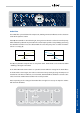
If the EQ Gain controller is turned hard right, the signal rates above the selected center frequency
will be boosted by 3dB and the part below the center frequency will be cut by 5dB [Fig. A]. Turning
the controller hard left reverses the eect: Below the center frequency there is a boost and above
it there is a cut [Fig. B].
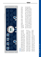
The EQ Freq controller comprehends an array from 20Hz - 2kHz which can be shifted to 200Hz
- 20kHz by pushing the x10 button.
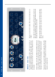
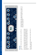
In the linked MS mode shown above it is possible to make dierent settings for the Audio lters
in the M and the S band. Again, the results can be listened to separately by using the Compressed
switches for each channel. However, in Stereo mode, both Audio lters should be set to the same
values in order to avoid unwanted shifts in the stereo spectrum.
Note: Depending on the settings of the Audio lters it might be necessary to adapt the volume
with the Gain controllers.
Soft Clip
Gain Reduction
MS Mode Active Channel Link
Mix
Gain
EQ Freq
Hz
SC Gain
dB
SC Freq
EQ Gain
Auto Fast
Feed Forward
On
Auto Fast
x10
On
Transformer
Direct
Compressed
On
Thresh Attack Release Ratio
Soft Clip
Mix
Gain
EQ Freq
SC Gain
dB
EQ Gain
Auto Fast
Feed Forward
On
Auto Fast
x10
On
Transformer
Direct
Compressed
On
Thresh
Attack
ms
Release
ms
Ratio
1:X
Soft Clip
SC Freq
Center Frequency
+
Gain
-
A
Left
Input
Compressor
Audio
Filter
Left
Output
Right
Input
Compressor
Sidechain
Audio
Filter
Right
Output
MS Encoder
S
M
Gain
Stage
L
R
MS Decoder
Gain
Stage
Center Frequency
+
Gain
-
B