
User manual


DC Controller
UPC4 Master
User Manual
Page 65/100
©2010. ELTEK VALERE DEUTSCHLAND GmbH. UM_UPC4_V2.00_E_R1.1_2011-01-04
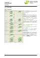
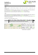
6.7.3 Signals Sw mode
In the area „Signals Sw mode“, the
configured lists can be inverted at their
outputs. Additional a time delay can be set.
It is common practice to let a relay operate
at failure free condition so that a cable
break can be recognised as failure. Due to
this fact, the relay output is inverted, e.g.
„Relay 1.1 = 1“.
If the green LED () shall glow if no fai
lure
occurs, the LED must be inverted too.
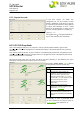
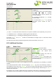
6.8 LVD/PLD/Drop diode
LVD = Low Voltage Disconnect. This function is mainly used to protect batteries against total
discharge. If the set under voltage limit is reached, the battery is disconnected from the system by
contactor.
PLD = P
riority Load Disconnect. By this function it is possible to early disconnect “unimportant” loads
at battery operation if the battery voltage under-runs voltage limit values. Consequently the backup
time of prioritized loads is increased.
Because the three areas for LVD, PLD1 and PLD2 are ne
arly identical, in the following the areas
exemplarily are explained on the basis of the LVD function.
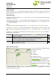
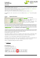
Parameter „Source select“ (20.4) decides
on the general LVD/PLD functionality.
Explanation of the figures:
0 (OFF) disabled
1-6
The measuring sources which are
assigned at "Assignment measured
values" are used as reference. The
thresholds "Low limit OFF" (20.1) and
"Low limit ON" (20.2) for detection refer
to that measuring value. These
thresholds are used only at this
configuration.
7 Switches the LVD/PLD function
depending on "battery operation" (see
section 6.6.1 "Thresholds").
8 (Mains error) only makes sense in
conjunction with the connection of an
external Mains Monitoring Board (MMB),
optional.
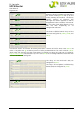
At recognition of LVD, PLD1, PLD2
respectively an event is generated which
can be assigned to any output (relay) at
“Signals enable
” (see section 6.7.2).
20.8
20.6
20.9
20.7
20.4
20.1
20.2
20.5
20.10