
User manual


DC Controller
UPC4 Master
User Manual
Page 63/100
©2010. ELTEK VALERE DEUTSCHLAND GmbH. UM_UPC4_V2.00_E_R1.1_2011-01-04
6.7 Outputs/Alarm signaling
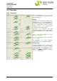
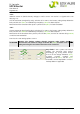
6.7.1 Digital inputs*
(*2.11 is required)
At "Digital inputs" a maximum up to 16
extern
al digital inputs can be configured.
Parameter (14.1)
*2.11
and (14.2)
*2.11
are for
the first digital input board (DIB), parameter
(14.3)
*2.11
and (14.4)
*2.11
are for the second
DIB.
At (14.1)
*2.11
and (14.3)
*2.11
the individual
inputs can be inverted, at (14.2)
*2.11
and
(14.4)
*2.11
the delay values are set.
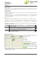
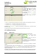
6.7.2 Signals enable
In the area „Signals enable“, all external and
internal failures and events respectively
can be enabled to an output. Thereby e.g.
relays or SNMP traps can be activated.
The events are grouped into the groups
Gener
al, System, Battery, and Fuses. They
are available to each output.
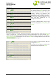
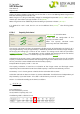
You can find a list of all individual failures
and eve
nts as well at section 7 "Event list
UPC4 (failure list)".
"Error state" (15.2) is of
particular importance. If an event of this list is active, the red LED "ALARM" of
the optional RDD and RDP respectively starts blinking.
Events which are active at "Event history" and "Modem/Traps" as well (16.
2) are signaled via SNMP.
At "Disable Signals" (15.1) several events can be disabled for all other lists.
14.1
14.2
14.3
14.4
15.1
15.2