
User manual

DC Controller
UPC4 Master
User Manual
Page 50/100
©2010. ELTEK VALERE DEUTSCHLAND GmbH. UM_UPC4_V2.00_E_R1.1_2011-01-04
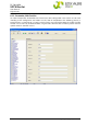
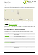
6.4.2 CAN Devices Cnt
A multitude of devices (modules) can be
connected to the UPC4 via CAN bus.
The number of the used rectifiers (2
.1) &
(2.20), DC/DC converters (2.2), and
inverters (2.3) can vary in the different
power supply systems. The most of the
modules automatically log on themselves at
the UPC4 and need'nt to be manually
configured.
Rectifiers of series PSS (2.1), DC/DC-
conver
ters PSC (2.2), and inverters of series
UNV (2.3) are excepted because they have
no automatic log on functionality.
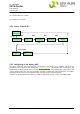
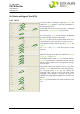
Each of the marked fields correspond to the
CAN a
ddress of one registered module (2.1),
(2.2), (2.3), (2.20). Due to the fact that not
all of the slots must be equipped, gaps within
the sequence can occur.
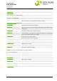
Two different rectifier families can be
controll
ed by the UPC4:
- "REC#1": (2
.1)
*2.19
that are modules
of series PSR and PSS.
- "REC#2": (2.20)
N*2.19
that are
modules of series Flat-, Mini-, Micro-,
and Powerpack.
The rectifier family which is used in the
UPC4
-controlled system has to be set at
parameter (2.19).
ATTENTION!
Either rectifiers of type according to "REC#1" or rectifiers of type according
to "REC#2" are allowed to be used within one system.
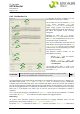
The interpretation of parameter REC#2 compared to the
parameters REC#1, INV, DCC is different. As
described above, REC#1 (2.1)
*2.19
, INV (2.3), DCC (2.2) have an automatic log on functionality.
Therefore each of the backplane slots have an explicid CAN address which results from the number of
the slot of the backplane in combination with the set CAN address of the backplane. That means that
each of the plugged modules can explicitely be allocated. As shown in the picture above as example,
REC#1, No. 1, is configured. That means that at the first slot of the first backplane a module is
expected.
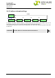
This is not possible for REC#2. No allocation of (2.20)
N *2.19
to the slots of the backplane is available.
The numbers of (2.20)
N *2.19
result from the temporal order of the plugged modules.
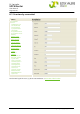
Redundancy:
At Systems with redundant rectifiers, DC/DC converters or inverters additional events can be
gener
ated by setting the parameters (2.4)
*2.19
, (2.5), (2.6), and (2.18)
N*2.19
.
Parameter (2
.4)
*2.19
is allocated to REC#1 (2.1)
2.19
whereas parameter (2.18)
N *2.19
is allocated to
2.1
2.2
2.3
2.7
2.8
2.20
2.4
2.5
2.6
2.18
2.19