DC Controller UPC4 Master USER MANUAL UM_UPC4_V2.00_E_R1.
DC Controller UPC4 Master User Manual Page 2/100 Notes to this manual ATTENTION! Read this manual carefully before installing and commissioning the specified unit. This manual is a part of the delivered unit. Familiarity with the contents of this manual is required for installing and operating the specified unit. The rules for prevention of accidents for the specific country and the general safety rules in accordance with IEC 364 must be observed.
DC Controller UPC4 Master User Manual Page 3/100 The current revision status of this user manual is the following: Revision: 1.1 Date: 2010-01-04 Revision Description of change Writer Date 0.0 Translation of the German version; proofreading version RTH 2010-12-02 1.0 First edition according to the development status of 2010-12-09 RTH 2010-12-09 1.1 Photos replaced, minor text modifications 2011-01-04 ©2010. ELTEK VALERE DEUTSCHLAND GmbH. RTH UM_UPC4_V2.00_E_R1.
DC Controller UPC4 Master User Manual Page 4/100 Contents 1 SAFETY INSTRUCTIONS & NOTES TO ELECTRONIC WASTE DISPOSAL ................................................... 7 2 GENERAL DESCRIPTION ....................................................................................................................... 8 3 TECHNICAL DESCRIPTION .................................................................................................................... 9 3.1 3.
DC Controller UPC4 Master User Manual Page 5/100 5.3 Operating status ..........................................................................................................................30 5.3.1 5.3.2 5.3.3 5.3.4 5.4 Control function............................................................................................................................33 5.4.1 5.4.2 5.4.3 5.4.4 5.4.5 5.4.6 5.4.7 5.5 Control function battery test ..................................................
DC Controller UPC4 Master User Manual Page 6/100 6.10.7 6.10.8 6.10.9 6.10.10 6.11 6.11.1 6.11.2 6.11.3 6.11.4 6.11.5 6.11.6 6.11.7 6.11.8 6.11.9 6.11.10 6.12 6.12.1 Fieldbus*...........................................................................................................................................................73 MMB*/Mains monitoring...............................................................................................................................74 Hand operation charge* .
DC Controller UPC4 Master User Manual Page 7/100 1 Safety instructions & notes to electronic waste disposal WARNING! Because several components of operating electric devices are charged by dangerous voltage, the improper handling of electric devices may cause accidents involving electrocution, injury, or material damages. Operation and maintenance of electrical devices must be performed by qualified skilled personnel such as electricians in accordance with EN 50110-1 or IEC 60950.
DC Controller UPC4 Master User Manual Page 8/100 2 General description The new DC controller UPC4 Master is an integrated unit for control, monitoring and signaling of battery-backed DC power supply systems. The unit is easy to use and programmable via display panel or RS232/Ethernet interface in combination with PC software. On the basis of a free programmable signal matrix, the customer is able to configure several alarms to groups and which of all the signaling outputs are to be used.
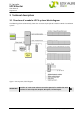
DC Controller UPC4 Master User Manual Page 9/100 3 Technical description 3.1 Structure of a modular UPC4 system/block diagram The following picture schematically shows the structure in principle of a modular CAN bus based UPC4 system. Figure 1. UPC4 system, block diagram IMPORTANT! Rectifiers of series PSR and PSS cannot be operated in combination with rectifiers of series Flatpack, Minipack, Micropack, and Powerpack. ©2010. ELTEK VALERE DEUTSCHLAND GmbH. UM_UPC4_V2.00_E_R1.
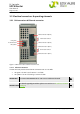
DC Controller UPC4 Master User Manual Page 10/100 3.2 Electrical connectors & operating elements 3.2.1 CAN connectors & Ethernet connector ON/OFF CAN connector 4 (RJ45) LED green Termination switch CAN connector 3 (RJ45) RJ 45 Ethernet LED yellow ON/OFF CAN connector 2 (RJ12) Termination switch CAN connector 1 (RJ12) Figure 2. CAN connectors & Ethernet connector 3.2.1.1 Ethernet connector The UPC4 Master provides one Ethernet connector RJ45 10/100 Mbit.
DC Controller UPC4 Master User Manual Page 11/100 3.2.1.2 CAN connectors (see also section 4.2 “Rectifier monitoring”) The UPC4 Master provides two different CAN bus systems (see also Figure 1.). CAN bus connectors as described in the following are available: 1. 100 kbit/proprietary protocol → two CAN connectors RJ12 (CAN 1 & CAN 2).
DC Controller UPC4 Master User Manual Page 12/100 3.2.2 Modem connector/Fieldbus connector/SD card slot/LED indications Hex switch 2 Push button 2 SD card slot Push button 1 Hex switch 1 LED 5 (green) LED 4 (orange) Male connector RS232 (Modem) Female connector RS485 (Mod-/Profibus) LED 3 (green) LED 2 (red) Dip switches OFF ON LED 1 (green) Figure 3. Modem connector/Fieldbus connector/SD card slot/LED indications 3.2.2.1 SD card slot REMARK: This functionality is not available at version 2.12.
DC Controller UPC4 Master User Manual Page 13/100 3.2.2.4 Fieldbus connectors The UPC4 Master provides two different fieldbus connectors: 1.) Fieldbus connector RS485 The female connector RS485 (see Figure 3.) is designed to connect Modbus (Profibus is not available at version 2.12). 11 10 Figure 4. Fieldbus female connector RS485 Pin assignment of the RS485 connector: Connector RS485 Pin 1 2 3 4 5 6 7 8 9 10 & 11 Function SHIELD Not used LINE B RTS GND +5V Not used Line A Not used SHIELD 2.
DC Controller UPC4 Master User Manual Page 14/100 3.2.2.6 Function of the dip switches The dip switches (see Figure 3.) are designed to terminate the field bus. By switching switch 1 to ON position the termination resistor of 120 Ω is enabled. That is necessary if the UPC4 master is one end of the field bus. In this case the field bus is either connected to the RS485 connector or to the MSTB connector. If both connectors are used or e.g.
DC Controller UPC4 Master User Manual Page 15/100 3.2.3 Power supply inputs/Relay outputs/MSTB Modbus connection 1 2 1 2 3 4 X2 (Power supply input 1) X8 (Modbus/Profibus) 1 2 X3 (Power supply input 2) 1 2 3 X12 (Relay 1) 1 2 1 2 3 X4 (Power supply input 3) X13 (Relay 2) 1 2 3 X14 (Relay 3) Figure 5. Power supply inputs/Relay outputs/MSTB Modbus connection 3.2.3.1 Power supply Three power supply inputs are available (see Figure 5.).
DC Controller UPC4 Master User Manual Page 16/100 The power supplies have to be connected to the inputs X2, X3, X4 according to the following table. Connector type: MSTBO 2.5, two-pole. Pin assignment of the power supply inputs: Connector X2 (Input 1) X3 (Input 2) X4 (Input 3) Pin 1 2 1 2 1 2 Function positive terminal (+) negative terminal (-) positive terminal (+) negative terminal (-) positive terminal (+) negative terminal (-) 3.2.3.
DC Controller UPC4 Master User Manual Page 17/100 4 The concept 4.1 General The UPC4 is a central control unit for the purpose of controlling the power system. The unit collects the data of CAN bus connected modules such as voltages, electric current values measured by basic units (BU), digital status information (via digital input board DCC-Di8) and status messages/values of the power modules (rectifiers, DC/DC converters, DC/AC inverters, static bypass switch (STS) etc.
DC Controller UPC4 Master User Manual Page 18/100 4.2.2 Rectifiers of the Flat-, Mini-, Micro-, and Powerpack group The UPC4 supports all rectifiers of the Flat-, Mini-, Micro-, and Powerpack group at its second CAN bus port "CAN 3 & CAN 4" (RJ45 connectors). Compared to the PSR rectifiers (see section 4.2.1 Rectifiers of the PSR/PSS group) the slots of the xxpack rectifiers have no fixed CAN addresses. Therefore the log on procedure between UPC4 and these types of rectifiers is different.
DC Controller UPC4 Master User Manual Page 19/100 4.2.4 Monitoring of rectifier load If the power system is equipped with more rectifiers as necessary (redundancy), these spare rectifiers can be configured as redundant. All rectifiers within the power system remain operating; merely the signalling is changed in the case of a unit failure. At the menu "CAN Devices Cnt" (section 6.4.2) two types of signaling concerning redundancy are settable. 1.
DC Controller UPC4 Master User Manual Page 20/100 4.3 Battery backup systems 4.3.1 Temperature controlled output voltage (Float charge of batteries in backup systems) U [V] 0°C 20°C 40°C T [°C] Figure 6. Diagram “Output voltage depending on temperature” For this operation mode a temperature sensor of type KTY 81- 220 which is connected to a BasicUnit BU is necessary.
DC Controller UPC4 Master User Manual Page 21/100 4.3.2 Charge current limitation Figure 7. Diagram “Charge current limitation” Discharged batteries, e.g. after backup operation, are charged with an adjustable maximum current until the value of the temperature-controlled trickle charge voltage is reached. The battery voltage is measured at the beginning of the battery charging.
DC Controller UPC4 Master User Manual Page 22/100 PLD recognition at detection of mains failure (requires MMB) after expiration of an adjustable time delay, reset after ending of mains failure. (For details please see section 6.8 LVD/PLD/Drop diode). 4.3.5 LVD function (total discharge protection) The LVD (Low Voltage Disconnection) function makes it possible to protect the batteries against total discharge.
DC Controller UPC4 Master User Manual Page 23/100 Thereby the batteries supply the connected load and consequently are discharged. Following criteria finish a battery test: achievement of test duration under-running of a battery voltage value maximum discharge battery capacity (%) The battery test is assessed as faulty and a respective event is generated, if the minimum test voltage has been achieved within the test duration or the maximal battery capacity has been withdrawn.
DC Controller UPC4 Master User Manual Page 24/100 (For details please see section 6.4.4 Service/Enable). During equalize charge the charge voltage is increased compared to the trickle charge voltage. Furthermore this charging mode is current-limited by a settable value. After the end-of-charge voltage is reached for a period of 40 minutes or a settable max. time value is reached, equalize charging is finished. (For details please see section 5.4.3 Equalize charge). 4.3.
DC Controller UPC4 Master User Manual Page 25/100 4.6 DC/AC inverters/static bypass switch) If inverters (with or without static bypass switch STS) are intergrated in the system, the status and failure messages respectively are provided by the UPC4 such as for the most of the other CAN devices.
DC Controller UPC4 Master User Manual Page 26/100 REMARK: Existing alarms can be cancelled only by remedy of the cause of the alarm. If an RDD or RDP is used, the red LED "ALARM" blinks as long as a minimum of one alarm is existend. 4.8.2 Event history All events which are allocated to this output are written into the event history list. They are there recorded including information such as start and stop of the event, date, and time.
DC Controller UPC4 Master User Manual Page 27/100 4.10 Automatic log on of rectifiers, inverters, DC/DC converters The following product families log automatically on at the UPC4: Rectifiers PSR, Flatpack 2, Micropack, Minipack, and Power Pack DC/DC converters of PSC series Inverters of INV series If one of those modules are plugged to a backplane, it logs automatically on to the UPC4 and therefore is controlled by the UPC4. If subsequently a module is removed or fails, an event is generated, e.g.
DC Controller UPC4 Master User Manual Page 28/100 5 The menu (display operation) Operation of the UPC4 takes place using a CAN bus-connected remote display (as option) or via remote control using the PC software Multi Management Tool (MMT) alternatively. As a standard four menu blocks are available as described as follows: 1. 2. 3. 4. Measured values Control functions Operating status System menu Section 5.4.7 “Log in“ describes how to log-in at the UPC4.
DC Controller UPC4 Master User Manual Page 29/100 x times ESC UPC4 12.07.10 OKAY 11:47:36 x times ▲ ENT ENT Measuring values ►Power Modules Power Modules ►Rectifier R#1 ▼ ENT (1)* R#1 1:OKAY Vo= 54.4 V ▼ ▼ ENT R#1 1:OKAY Io=11.5 A R#1 1:OKAY T= 43C° ENT ENT R#1 2:OKAY Vo= 54.4 V R#1 2:OKAY Io=11.5 A R#1 2:OKAY T= 43C° ▼ R#1 3…96 ENT Power Modules ►DC/DCConverters DCC1:OKAY Vo= 54.4 V ▼ ENT DCC1:OKAY Io=11.
DC Controller UPC4 Master User Manual Page 30/100 Rectifiers of the series PSR & PSS are in the group "R#1". The abbreviation for those rectifiers is "R#1". Rectifiers of the series Micro-, Mini-, Flat-, and Powerpack are in the group "R#2". The abbreviation for those rectifiers is "R#2". 5.3 Operating status In this menu block information about the actual operating status of the system can be queried.
DC Controller UPC4 Master User Manual Page 31/100 5.3.2 Failure list (1)* 2x ESC UPC4 12.07.10 ERR 11:47:36 x times▼ Operating Status ►Failure List ENT (2)* Vlo < Vmin 3000 1(5) ▲ Vis < Vmin_INV 3002 2(5) ▲ More failures (1)* "The failure LED at the RDP or RDD is active"; "ERR" at the display indicates that one or more failures (alarms) are existing. (2)* Shows the active failure. The first number (e.g. 3000 as shown in the example above) indicates the explicit event number.
DC Controller UPC4 Master User Manual Page 32/100 5.3.4 Operating status "Modem" (Only available if „enable modem“ is configured). 1. Modem configured. Modem status is stopped. Direct communication via RS232 is possible. Modem operation not possible. 2. Modem configured. Modem status is started. Direct communication via RS232 is not possible. Exclusively modem operation is possible. 2x ESC UPC4 12.07.10 OKAY 11:47:36 x times▼ Operating status ► Modem ENT (1)* Int: (2)* Int: .
DC Controller UPC4 Master User Manual Page 33/100 "I"= initialised "i"= not initialised During starting the UPC4 and during starting initialisation, the first character is “*”, the final character is “i”. After a time period the first character is “.”, the final character is “I”. This indicates a successful initialisation. 5.4 Control function UPC4 functions which are enabled can be executed in this menu block. Control function: Battery Test: Start/stop battery test, deleting of battery test failures.
DC Controller UPC4 Master User Manual Page 34/100 Manual stop UPC4 12.07.10 OKAY 11:47:36 x times ▼ ENT Control Function ►Battery Test ENT (1)* Battery Test ↕ Battery Test Stop?->ENTER ENT (2)* (1)* "Log in" could be necessary, see section 5.4.7 Log in. (2)* Battery test is stopped. Clear battery test error 3 times ESC UPC4 12.07.
DC Controller UPC4 Master User Manual Page 35/100 Stop UPC4 12.07.10 OKAY 11:47:36 x times ▼ Control Function ►Boost charge ENT(1)* Boost charge Stop?->ENTER ENT (2)* (1)* "Log in" could be necessary, see section 5.4.7 Log in. (2)* Boost charge is stopped. 5.4.3 Control function "equalize charge" (Only available if "equalize charge" is enabled). Start UPC4 12.07.
DC Controller UPC4 Master User Manual Page 36/100 5.4.4 Control function "Hand-op. charge" (Only available if "Hand-op. charge" is enabled). 2x ESC UPC4 12.07.10 OKAY 11:47:36 x times ▼ ENT (1)* Hand-op. char start Act.: 20.0A 54,0V Control Function ► Hand-op. char ▼▲ Automatic (2)* Nomin.: 54,0V Act.:20.0A 54,0V (3)* ENT (4)* Nomin.: 54,2V Act.:20.0A 54,2V Hand-op. char start Act.: 20.0A 54,2V (1)* "Log in" could be necessary, see section 5.4.7 Log in.
DC Controller UPC4 Master User Manual Page 37/100 5.4.6 Control function "modem" (Only available if "modem" is enabled). Start UPC4 12.07.10 OKAY 11:47:36 x times ▼ ENT Control Function ► Modem Modem Opera Start?->ENTER ENT (1)* (1)* Modem is started, i. e. the UPC4 operates in the modem mode. Stop UPC4 12.07.10 OKAY 11:47:36 x times ▼ ENT Control Function ► Modem Modem Opera Stop?->ENTER ENT (1)* (1)* Modem is stopped, i. e. the UPC4 dos not operate in the modem mode.
DC Controller UPC4 Master User Manual Page 38/100 5.4.7 Log in (1)* ENT Login Procedure User1 ▲ Login Procedure User2 (2)* ▲▼ User: User1 Passwd: a (3)* User: User1 Passwd: ****r ▲▼ ENT User: User2 Passwd: a User: User2 Passwd: ****r ▲ User3…7 (4)* (1)* If within the menue an action is to be carried out which requires expanded access right (such as e.g. delete Event list , see section 5.3.1), the log in procedure is automatically called.
DC Controller UPC4 Master User Manual Page 39/100 5.5 Secondary menu Using the secondary menu, the status and the configuration parameters of the UPC4 are visible and can be changed after authorization, see section 5.5.3 Configuring at the display/MMT. Control Function2nd Menu: Error list: All present errors (failures) History list: The last 500 incoming and outgoing failures/events Information menu o Indicator measuring param.: Shows all available measuring objects Config.
DC Controller UPC4 Master User Manual Page 40/100 5.5.1 Date, time, illumination, contrast, and lamp test UPC4 12.07.10 OKAY 11:47:36 x times ▼ Control function ►Sekundar menu ▼ ►Error List History List ▼ ►Config UPC4 Controlfunction ENT ENT ►Date & Time Display backli ▼▲ (1)* 12.07.2010 11:47:36 13.07.
DC Controller UPC4 Master User Manual Page 41/100 (4)* The set contrast is stored. (5)* Lamp test is finished. 5.5.2 Status “Default OK” UPC4 12.07.10 OKAY 11:47:36 ENT ENT x times ▼ Control function ►Sekundar menu ►Error list History list ENT ►Controlfunction Display Systemp ENT ►Statusdefault OK Rectifiers BLINK ►Statusdefault OK ENT automatically ►Statusdefault OK WAIT…OK ►Statusdefault OK OKAY 5.5.
DC Controller UPC4 Master User Manual Page 42/100 5.6 IP address/network settings 2x ESC UPC4 12.07.10 OKAY 11:47:36 ▲ ENT x times ▼ Control funktion ►LAN Parameter IP 192.168.0.123 ▲ ▲ Netmask 255.255.255.0 Gateway 0.0.0.0 DNS-Server 0.0.0.0 IP address and other network settings as well cannot be set at the display. Either they can be configured by MMT or by the use of the software "Eltek Valere Network Utility".
DC Controller UPC4 Master User Manual Page 43/100 6 Configuration – UPC4 6.1 General Information Because direct configuration at the UPC4 control unit (display panel) is not practice-oriented (see section 5.5.3) please use the PC software "Multi Management Tool" (MMT) free of charge. The UPC4 provides an Ethernet interface (RJ45), a serial interface RS232 and optional a connection via modem is possible as well.
DC Controller UPC4 Master User Manual Page 44/100 6.1.2 UPC4 parameter groups REMARK: The pictures shown in the following are screenshots of the configuration software MMT. The "hide function" is enabled for the following picture (see also the following page). After successful readout/start of a configuration a register of the parameter groups is shown to the left of the screen (MMT configurator). A selected group (via left mouse button) is shown to the right. Parameter groups ©2010.
DC Controller UPC4 Master User Manual Page 45/100 6.1.3 Parameter, hide function To make the operation comfortable for the end-user, MMT configuration areas which are not used according to the configuration are hidden. For the sake of completeness the following picture as example shows a screenshot of a system in which all areas are used and therefore are visible. The hide function can be manually enabled/disabled using the MMT software tool. For details please read the specific section in the MMT manual.
DC Controller UPC4 Master User Manual Page 46/100 Parameters which effect that other areas are hidden/unhidden are marked green. Those parameters which can be hidden due to this are marked blue (see the following picture please). The concerned parameters are represented in this manual by a number followed by a superscripted "N" or a star (*) and a superscripted number in addition. Example 1: "1.10)*1.6": That means that the parameter 1.6 must be enabled in order to make parameter 1.10 visible (see 6.
DC Controller UPC4 Master User Manual Page 47/100 Digital inputs* (section 6.7.1) Signals enable (section 6.7.2) Signals Sw mode (section 6.7.3) Inversion and/or time delay of digital inputs DIB (*DIB is required) Configuration of events, LEDs, and relays inverting/delaying of output signals LVD/PLD/Drop diode (section 6.8) LVD/PLD/Drop d. Setting of LVD/PLD & drop diode functions Remotedisplay (section 6.
DC Controller UPC4 Master User Manual Page 48/100 6.3 Overview by screenshot UPC 4 Installation UPC4 CAN Devices Cnt Service/Enable Charge control Syst parameters Thresholds Assignment Measu Assignment Shunt* Battery Battery Test* Equalize charge* Boost charge* Capacity Calc.* Signals enable Signals Sw mode LVD/PLD/Drop d. Mains monitoring Digital inputs* RD/RDP Remote SNMP* Field bus* Modem* Thresh. Gen. par Hand-op. charge* System test* Text Syst param Text Batt param.
DC Controller UPC4 Master User Manual Page 49/100 6.4 Basic settings of the UPC4 6.4.1 UPC4 The text, which is entered in Logo line 1 (1.1) and Logo line 2 (1.2) appears as text for information at the display of the unit. 1.1 1.2 1.3 1.4 Information about the firmware version is indicated by the fields (1.3), (1.4), (1.5). (Only to read). 1.5 At "Time source" (1.6) can be choosen, wherefrom the internal clock shall be synchronized. 1.6 At (1.7)*1.
DC Controller UPC4 Master User Manual Page 50/100 6.4.2 CAN Devices Cnt A multitude of devices (modules) can be connected to the UPC4 via CAN bus. 2.19 The number of the used rectifiers (2.1) & (2.20), DC/DC converters (2.2), and inverters (2.3) can vary in the different power supply systems. The most of the modules automatically log on themselves at the UPC4 and need'nt to be manually configured. 2.1 2.2 Rectifiers of series PSS (2.1), DC/DCconverters PSC (2.2), and inverters of series UNV (2.
DC Controller UPC4 Master User Manual Page 51/100 REC#2 (2.20) N *2.19 . Two modes are available for the evaluation of the redundancy which can be set in the menu Special set, see section 6.12.1. The following example relates to rectifiers REC#1 but is valid for rectifiers REC#2, DC/DC converters, and inverters as well. Redundancy mode= UPC3/MU2000 (see item 35.3 at section 6.12.1). Redundancy event is active as soon as no redundancy is existent. Example: System with seven registered rectifiers (2.
DC Controller UPC4 Master User Manual Page 52/100 Optional CAN devices (modules): CAN device item Comment BU Basic Unit (2.7) Modular measuring board. E.g. for battery monitoring STS Bypass (2.8) Active Static Bypass Switch (mains <—> inverter) MMB MainsMonitor (2.9) Mains monitoring (AC input) BMB AnalogInputs (2.10) Extension of the measuring inputs for battery monitoring DIB Digital Input (2.11) Extension of the digital inputs RLB Relais Outp (2.
DC Controller UPC4 Master User Manual Page 53/100 6.4.4 Service/Enable 7.1 In the area „Service/Enable“, additional functions can be enabled at the UPC3. If a parameter is set to „0“, the function is disabled. If a parameter is set to “1” or greater, the function is enabled. A battery test (7.1) can be started/stopped in different ways at the UPC4: 7.2 7.
DC Controller UPC4 Master User Manual Page 54/100 (7.4) and (8.2). At "Start" the digital input to start the function is set, at "Stop/Inhibit" the digital input to stop/inhibit the function is set. DIB extension module(s) are necessary. 9.1 9.2 9.3 9.4 9.5 9.8 9.6 9.11 9.9 9.7 9.10 By enabling the parameter „Hand-op. charge” (9.1) a manual control of the default voltage of the rectifiers is possible. Enabling "System test“ (9.
DC Controller UPC4 Master User Manual Page 55/100 6.4.5 System parameters 4.1 4.3 4.5 4.4 4.2 4.6 4.10 4.9 4.7 4.8 4.11 "REC Nom. voltage" (4.1) is the float charge voltage. In systems in which no batteries are used it simply is the default voltage of the rectifiers. "REC Boost chge V" (4.2)*8.1 is the boost charge voltage, whereas "REC Equalize Vol" is the equalize charge voltage (4.3)*7.3.
DC Controller UPC4 Master User Manual Page 56/100 6.4.6 Battery 5.1 In this menu the battery relevant settings are done. Battery count respectively available batteries are set at (5.1). "0"= not available, "1"= available. At (5.2) the nominal capacity value of the battery, at (5.3) the number of the battery cells (cell count) is set. 5.3 5.2 5.4 5.5 ©2010. ELTEK VALERE DEUTSCHLAND GmbH.
DC Controller UPC4 Master User Manual Page 57/100 Legend: Vtapp = Measured tapped voltage value against (–) Vbatt = Measured battery voltage Batc = Number of batteries (value has to be set) Ctapp = Tapping point counted from (-), value has to be set Vplus = Calculated tapped voltage value against (+) (a) Asymmetry calculation with tapping point at the center of the battery: Diff Vbatt 2 xVtapp If the difference (without consideration of sign) is greater than (5.
DC Controller UPC4 Master User Manual Page 58/100 Example: Vload Vnom Tk * N cell * t (Tk = -4mV/cK; Ncell=24; t=+5°K are used for this example). Vload 54,3V (0,004) * 24 * 5 Vload 53,8V at 30C If the currently measured temperature value is below (6.6), then this value is used for temperature compensation. If the currently measured temperature value is above (6.7), then this value is used for temperature compensation. 6.5 Measuring system 6.5.
DC Controller UPC4 Master User Manual Page 59/100 Explanation of the measuring values: (Important default assignments are listed below. For a list of all available measurement sources see Section 7 please). Batteries: "Voltage Vbatt", "Tapp voltage Vtapp", "Current Ibatt", "Battery temperat.": At this menu items the measurement sources concerning battery measurements have to be assigned. A maximum of seven batteries can be monitored by the UPC4.
DC Controller UPC4 Master User Manual Page 60/100 6.5.2 Assignment Shunt* (*2.7 or 2.10 is required) 9.11 In this menu the values of the connected shunts are configured. The value of 60 A (see the left-hand picture) means: If a voltage value of 60mV falls at the shunt it is interpreted as a current flow of 60 A. The current values of the Basic-Units (BU) are set at (9.11)*2.7. 9.12 The current values of the Monitoring Boards (BMB) are (9.12)*2.10. ©2010. ELTEK VALERE DEUTSCHLAND GmbH.
DC Controller UPC4 Master User Manual Page 61/100 6.6 Thresholds 6.6.1 Thresholds 10.1 10.2 10.3 With the exception of (10.4), (10.20) and (10.21) all settings in this group serve for generating events. Battery 10.4 10.5 10.6 10.7 10.8 10.9 Exceeding the threshold of battery over voltage "Vmax" (10.1) or falling below the threshold of battery under voltage "Vmin" (10.2) respectively battery warning voltage "Vwarn" (10.3) activates the related event in the signal matrix. Parameter (10.
DC Controller UPC4 Master User Manual Page 62/100 Battery operation Battery operation (10.12) is detected by negative battery current flow. Because of measuring inaccuracy the threshold should be ≥5% of the shunt value. At (10.14) hysteresis and at (10.13) delay is to be set. Isolation measuring Enabling as well as assignment is set in these menus. At this place the threshold for detecting isolation error is defined. Isolation error measuring (10.15) is only possible at ungrounded systems.
DC Controller UPC4 Master User Manual Page 63/100 6.7 Outputs/Alarm signaling 6.7.1 Digital inputs* (*2.11 is required) 14.1 14.2 14.3 At "Digital inputs" a maximum up to 16 external digital inputs can be configured. Parameter (14.1)*2.11 and (14.2)*2.11 are for the first digital input board (DIB), parameter (14.3)*2.11 and (14.4)*2.11 are for the second DIB. At (14.1)*2.11 and (14.3)*2.11 the individual inputs can be inverted, at (14.2)*2.11 and (14.4)*2.11 the delay values are set. 14.4 6.7.
DC Controller UPC4 Master User Manual Page 64/100 16.1 16.2 16.3 All events which have been activated in the list „Events history“(16.1) end up on the history memory of the UPC4. The history memory contains of maximum 500 messages and stores appeared as well as disappeared events. Readout and reset of this list takes place either directly at the RDD and RDP respectively or via configuration software. 16.4 16.5 The three available internal relays of the UPC4 are configured at (16.5), (16.6), and (16.
DC Controller UPC4 Master User Manual Page 65/100 6.7.3 Signals Sw mode In the area „Signals Sw mode“, the configured lists can be inverted at their outputs. Additional a time delay can be set. It is common practice to let a relay operate at failure free condition so that a cable break can be recognised as failure. Due to this fact, the relay output is inverted, e.g. „Relay 1.1 = 1“. If the green LED () shall glow if no failure occurs, the LED must be inverted too. 6.
DC Controller UPC4 Master User Manual Page 66/100 "LVD": Selection source V1 (default battery voltage) as well as event “LVD active” is assigned to the LVD relay (e.g. K1). The LVD contactor (energized by relay) switches off as soon as the battery voltage drops below the limit „Low limit OFF“ (20.1) and additionally "Drop delay" (20.5) has been elapsed. Reactivation of the contactor takes place if „Low limit ON“ (20.2) has been exceeded.
DC Controller UPC4 Master User Manual Page 67/100 6.9 Remote Display 22.1 22.3 22.4 22.5 22.2 In this area general settings can be made concerning RD and RDP as well. At (22.1) LCD contrast, at (22.2) ilumination is set. In the area "Alternate Display" it can be set what should be displayed first on the display: It is possible to display element 1 = Status + time, element 2 = load values (voltage/current) or element 3 = LOGO and/or element 4 = battery remaining time.
DC Controller UPC4 Master User Manual Page 68/100 23.1 For RDP only: 23.2 On the Remote Display Panel definite block diagrams are used. For detailed information please see the specific user manual of the RDP. 23.3 By parameter "Enable RDP" (23.1) the RDP can be enabled. 23.4 At "StartUP action" (23.2)*23.1 it is set how the UPC4 system should act after a restart. „0 = none“ >> no command to the CAN devices. The present condition “ON” respectively “OFF” persists.
DC Controller UPC4 Master User Manual Page 69/100 6.10.2 Equalize Charge* (*requires 7.3), see section 6.4.4. 40.1 Enabling "Equalize charge" in general is already described at Service/Enable. In this menu the duration of "Equalize charge" (40.1)*7.3 has to be set. 40.2 40.3 Furthermore it is possible to start "Equalize charge" at a definite time (40.2)*7.3. Via parameter (40.3)*7.3 it can regularly be repeated according to the set interval (day(s)). Enabling has to be set at Service/Enable. 6.10.
DC Controller UPC4 Master User Manual Page 70/100 ignores the date and boost charge will start at the time as set. In the following boost charge will be executed according to the interval as set. Boost charge runs as long as the battery voltage has exceeded the parameter (27.8)*8.1 over (27.9)*8.1 seconds plus the "Follow up charge duration" as set (27.10)*8.1. Boost charge time can be additionally limited according to parameter "Timeout" (27.11)*8.1.
DC Controller UPC4 Master User Manual Page 71/100 Estimation of the discharge current Calculation (example): Battery 50 Ah Nominal capacity 95% (5.2), see section 6.4.6. Capacity= 47,5 Ah Example: 20A are withdrawn from the fully charged battery for more than one minute. For the calculation of factor F the accordant current values are used.
DC Controller UPC4 Master User Manual Page 72/100 2(1).system(1).sysDescr(1) is answered with „UPC4 Application“. But if a text is typed in, this text is used. The password for SNMP read authorisation has to be set at (29.2)*9.7, the password for SNMP write authorisation has to be set at (29.3)*9.7. Up to ten trap receivers (29.4)*9.7 can be configured. All IPs unequal to "0.0.0.0" are used. 6.10.6 Modem* (* requires 9.6), see section 6.4.4. 30.1 30.2 30.3 30.
DC Controller UPC4 Master User Manual Page 73/100 Token (UPC4 commands) %m %d %p %t40 %t %t0 %t100 %t400 %O %C %0 %% Sending without \r\n and waiting for answer from the modem 1 s pause 0.25 s pause Timeout 40 s Default 5 s (1-99 s) Timeout 320 ms min = 320 ms ditto ditto Timeout 400 ms 320 ..
DC Controller UPC4 Master User Manual Page 74/100 6.10.8 MMB*/Mains monitoring MMB* (requires 2.9), see section 6.4.2. 32.1 32.2 32.6 In connection with an optional available Mains Monitoring Board (MMB) the UPC4 is able to detect mains failure or phase break down. The mains failure is available as event and can also be used as source for „PLD/LVD“ function, see section 6.8. By the use of mains monitoring boards the voltages of each phase are measured. 32.3 32.5 32.4 The threshold values V< (32.
DC Controller UPC4 Master User Manual Page 75/100 6.10.9 Hand operation charge* 33.1 33.2 33.3 33.4 33.5 33.6 Enabling of "Hand operation charge" has to be set at Service/Enable (*requires 9.1), see section 6.4.4. During hand operation charge the automatic control of the rectifiers is invalid and therefore it is possible to charge the batteries manually using the RDD and RDP as well. In this case the user has to set the charge voltage value manually at the RDD/RDP.
DC Controller UPC4 Master User Manual Page 76/100 6.11 UPC4 Text 6.11.1 Installation In this menu the texts which describe the system (“Installation”) can be changed. 6.11.2 Text System parameter Self-defined texts which are used for the system and load respectively. These user-specified texts are also displayed according to the related measuring values at the RD display. 6.11.3 Text battery parameter* (*requires 5.1), see section 6.4.6. Self-defined texts which are used for the batteries.
DC Controller UPC4 Master User Manual Page 77/100 6.11.5 Text Digital input* (* requires 2.11), see section 6.4.2. 38.1 If digital input boards (DI8) are used, it is possible to assign individual texts to the digital inputs. These texts then also appear in the failure/event list. 38.2 For each individual digital input two texts are available. Text 1 is used if an event is active, text 2 is used if an event is inactive. 38.3 The texts (38.1)*2.11, (38.3)*2.
DC Controller UPC4 Master User Manual Page 78/100 6.11.6 Text Relay output 39.1 The texts are used in the menu "Relay Status" of the UPC4. The parameters (39.1), (39.4) are used for the internal relays of the UPC4. The texts of the relays of the optional BU(s) are set at (39.2)*2.7, (39.5)*2.7. 39.2 The texts of the optional relay boards (RB6) are set at (39.3)*2.12, (39.6)*2.12. If the event (e.g. relay 1.1) is active, the related fail texts (39.1), (39.2)*2.7, (39.3)*2.12 are used. 39.3 39.
DC Controller UPC4 Master User Manual Page 79/100 6.11.8 Text General parameters >>User defined texts, which are used for general measuring values. ATTENTION! 6.11.9 If no text is keyed in, the measuring value is disabled and is not used in the UPC4. Module IDtexts 1 >> All texts are for information only and can not be changed. The UPC4 receives the texts from the connected modules automatically. These texts are received from power modules such as PSR rectifiers, PSC, INV etc. 6.11.
DC Controller UPC4 Master User Manual Page 80/100 6.12 Miscellaneous parameters 6.12.1 Special Set Logging of measurement data Via Syslog Protocol UDP Port 514 measuring values can permanently be sent to a Syslog Server (35.2) *35.1. 35.1 35.2 35.4 35.3 ©2010. ELTEK VALERE DEUTSCHLAND GmbH. At (35.1) the cycle (seconds) is set. At (35.4)*35.1 the measuring sources are specified. Redundancy mode At (35.3) the redundancy mode is set. For details please see CAN Devices Cnt, see section 6.4.2.
DC Controller UPC4 Master User Manual Page 81/100 7 List of all available measurement sources NOTE: "X" in the table elements means that these parameters/elements are not factory defaultassigned.
DC Controller UPC4 Master User Manual Page 82/100 30 BU3_I2 General current 31 32 33 BU3_I3 BU3_T1 BU3_T2 34 35 BU 3 Current terminal I2 X X Battery temperat Battery 3 General temp.
DC Controller UPC4 Master User Manual Page 83/100 75 76 BU7_V2 BU7_V3 77 78 79 80 81 82 83 84 BU7_I1 BU7_I2 BU7_I3 BU7_T1 BU7_T2 Zero value BU7_Risol BU7_Visol 85 86 87 88 Zero value BU8_V1 BU8_V2 BU8_V3 89 90 91 92 93 94 BU8_I1 BU8_I2 BU8_I3 BU8_T1 BU8_T2 Zero value 95 BU 7 BU 7 Voltage terminal V2 Voltage terminal V3 BU 7 BU 7 BU 7 BU 7 BU 7 X BU 7 BU 7 Current terminal I1 Current terminal I2 Current terminal I3 Temperature sensor terminal T1 Temperature sensor terminal T2 BU 8 BU 8 BU 8 Vo
DC Controller UPC4 Master User Manual Page 84/100 119 120 121 122 123 124 125 126 127 128 129 130 131 132 133 134 135 136 137 138 MMB2_IL2 MMB2_IL3 Not defin. DEB1_stat DEB1_2 DEB1_3 DEB1_4 DEB2_stat DEB2_2 DEB2_3 DEB2_4 RLB1_stat RLB1_2 RLB1_3 RLB1_4 RLB2_stat RLB2_2 RLB2_3 RLB2_4 BMB1_Vbatt Mains currents Mains currents Inex.
DC Controller UPC4 Master User Manual Page 85/100 170 . . . . . . . . 249 250 UMB1_1 . . . UMB4_4 UMA1_1 . . . UMA16_4 SystIbatt 1 251 252 SystIrect 1 SystIload 1 Inex. Inex. ©2010. ELTEK VALERE DEUTSCHLAND GmbH. Universal measurement controller, device 1. It has been designed for universal usage. But it is currently not used. Universal measurement controller, device 2. It has been designed for universal usage. But it is currently not used. Calculated battery current. Result= Systlrect.
DC Controller UPC4 Master User Manual Page 86/100 8 Event list UPC4 (failure list) 8.1 General Eventno. 2000 Event text 2001 Dig. input 1[2] 2002 Dig. input 1[3] 2003 Dig. input 1[4] 2004 Dig. input 1[5] 2005 Dig. input 1[6] 2006 Dig. input 1[7] 2007 Dig. input 1[8] 2008 Dig. input 2[1] 2009 Dig. input 2[2] 2010 Dig. input 2[3] 2011 Dig. input 2[4] 2012 Dig. input 2[5] 2013 Dig. input 2[6] 2014 Dig. input 2[7] 2015 Dig.
DC Controller UPC4 Master User Manual Page 87/100 2074 2080 V5 <> Vmin/max5 V6 <> Vmin/max6 I1 <> Imin/max1 2081 I2 <> Imin/max2 2082 I3 <> Imin/max3 2083 I4 <> Imin/max4 2084 I5 <> Imin/max5 2085 I6 <> Imin/max6 2090 2128 T1 <> Tmin/max1 T2 <> Tmin/max2 T3 <> Tmin/max3 T4 <> Tmin/max4 T5 <> Tmin/max5 T6 <> Tmin/max6 R1 <> Rmin/max1 R2 <> Rmin/max2 R3 <> Rmin/max3 R4 <> Rmin/max4 R5 <> Rmin/max5 R6 <> Rmin/max6 Relay1.Q see event no. 2070 above see event no. 2070 above see event no.
DC Controller UPC4 Master User Manual Page 88/100 2134 Relay4.Q n/a 2135 Relay4.
DC Controller UPC4 Master User Manual Page 89/100 2188 1.L1 V<>Vmin,max see Mains monitoring 2189 see Mains monitoring 2194 1.L2 V<>Vmin,max 1.L3 V<>Vmin,max 2.L1 V<>Vmin,max 2.L2 V<>Vmin,max 2.L3 V<>Vmin,max error bool seq.
DC Controller UPC4 Master User Manual Page 90/100 8.2 System Eventno.
DC Controller UPC4 Master User Manual Page 91/100 3067 Capacity low A s. Capacity Calc. This event is active if the capacity of the batteries of system [1] which is calculated by the capacity calculator is less than threshold A (%). This signal is a warning signal. 3068 3070 Capacity low B Tsensor lim Batt s. Capacity Calc. 3073 diesel operation s.
DC Controller UPC4 Master User Manual Page 92/100 8.3 Battery Eventno. 4100 4101 4102 4103 4107 4108 4109 4110 Event text Reference to parameter Description Vbatt < Vmin(B1) Vbatt > Vmax(B1) Vbat < Vwarn(B1) Vbat > VmaxR(B1) T > Tmax(B1) Asymmetrical(B1) Fuse open(B1) Battery oper(B1) s. s. s. s. s. s. s. s.
DC Controller UPC4 Master User Manual Page 93/100 4600 4601 4602 4603 4607 4608 4609 4610 4700 4701 4702 4703 4707 4708 4709 4710 Vbatt < Vmin(B6) Vbatt > Vmax(B6) Vbat < Vwarn(B6) Vbat > VmaxR(B6) T > Tmax(B6) Asymmetrical(B6) Fuse open(B6) Battery oper(B6) Vbatt < Vmin(B7) Vbatt > Vmax(B7) Vbat < Vwarn(B7) Vbat > VmaxR(B7) T > Tmax(B7) Asymmetrical(B7) Fuse open(B7) Battery oper(B7) s. Event no. 4100 s. Event no. 4101 s. Event no. 4102 s. Event no. 4103 s. Event no. 4107 s. Event no. 4108 s. Event no.
DC Controller UPC4 Master User Manual Page 94/100 6021 6022 6023 6024 6025 6026 6027 6028 6029 6030 6031 6032 6033 6034 6035 6036 6037 6038 6039 6040 6041 6042 6043 6044 6045 6046 6047 6048 6049 6050 6051 6052 6053 6054 6055 6056 6057 6058 6059 6060 6061 6062 6063 6064 6065 6066 6067 6068 6069 6070 6071 6072 6073 Fuse 22 Fuse 23 Fuse 24 Fuse 25 Fuse 26 Fuse 27 Fuse 28 Fuse 29 Fuse 30 Fuse 31 Fuse 32 Fuse 33 Fuse 34 Fuse 35 Fuse 36 Fuse 37 Fuse 38 Fuse 39 Fuse 40 Fuse 41 Fuse 42 Fuse 43 Fuse 44 Fuse 45 Fus
DC Controller UPC4 Master User Manual Page 95/100 6074 6075 6076 6077 6078 6079 6080 6081 6082 6083 6084 6085 6086 6087 6088 6089 6090 6091 6092 6093 6094 6095 6096 6097 6098 6099 6100 6101 6102 6103 6104 6105 6106 6107 6108 6109 6110 6111 6112 6113 6114 6115 6116 6117 6118 6119 6120 6121 6122 6123 6124 6125 6126 Fuse 75 Fuse 76 Fuse 77 Fuse 78 Fuse 79 Fuse 80 Fuse 81 Fuse 82 Fuse 83 Fuse 84 Fuse 85 Fuse 86 Fuse 87 Fuse 88 Fuse 89 Fuse 90 Fuse 91 Fuse 92 Fuse 93 Fuse 94 Fuse 95 Fuse 96 Fuse 97 Fuse 98 Fus
DC Controller UPC4 Master User Manual Page 96/100 6127 6128 6129 6130 6131 6132 6133 6134 6135 6136 6137 6138 6139 6140 6141 6142 6143 6144 6145 6146 6147 6148 6149 6150 6151 6152 6153 6154 6155 6156 6157 6158 6159 6160 6161 6162 6163 6164 6165 6166 6167 6168 6169 6170 6171 6172 6173 6174 6175 6176 6177 6178 6179 Fuse 128 Fuse 129 Fuse 130 Fuse 131 Fuse 132 Fuse 133 Fuse 134 Fuse 135 Fuse 136 Fuse 137 Fuse 138 Fuse 139 Fuse 140 Fuse 141 Fuse 142 Fuse 143 Fuse 144 Fuse 145 Fuse 146 Fuse 147 Fuse 148 Fuse 1
DC Controller UPC4 Master User Manual Page 97/100 6180 6181 6182 6183 6184 6185 6186 6187 6188 6189 6190 6191 Fuse 181 Fuse 182 Fuse 183 Fuse 184 Fuse 185 Fuse 186 Fuse 187 Fuse 188 Fuse 189 Fuse 190 Fuse 191 Fuse 192 see see see see see see see see see see see see CAN devices CAN devices CAN devices CAN devices CAN devices CAN devices CAN devices CAN devices CAN devices CAN devices CAN devices CAN devices ©2010. ELTEK VALERE DEUTSCHLAND GmbH. Fuse error, signalled by FMB.
DC Controller UPC4 Master User Manual Page 98/100 9 Technical Data UPC4 Type DC Controller UPC4 Master Article code 301-004-395.00 Supply voltage 3 x redundant power supply inputs 24 VDC ±10 % by external power supplies DC/DC or AC/DC Voltage measuring range 0-320 VDC by Basic-Unit Current measuring range ±0-60 mV (shunt value programmable) by Basic-Unit Power consumption Max. 25 W LED indications 5 LEDs Relay outputs 3 (isolated; max. 0.5 A @ 60 VDC), plus 1 per Basic-Unit (isolated; max.
DC Controller UPC4 Master User Manual Page 99/100 9.1 Options Article code Designation 302-UP4-DCDC.LV Power supply, DIN rail mounting, Vi=18-75 VDC; Vo=24 VDC, Imax=2.5 A 302-UP4-DCDC.HV Power supply, DIN rail mounting, Vi=85-375 VDC; Vo=24 VDC, Imax=2.5 A 301-004-395.10 Basic-Unit (BU), 3 x voltage (0-300 V), 3 x current (60 mV shunt), 2 x temperature, one output relay, one LVD optocoupler control output 302-UP3-MMT.00 Configuration software “Multi Management Tool” (MMT) 302-003-RDD.
Supplier: FAX Email Internet ELTEK VALERE DEUTSCHLAND GmbH GB Industrial Schillerstraße 16 D-32052 Herford + 49 (0) 5221 1708-210 + 49 (0) 5221 1708-222 Info.industrial@eltekvalere.com http://www.eltekvalere.com Changes and errors excepted. 2010. ELTEK VALERE DEUTSCHLAND GmbH. All rights reserved.