DC/AC INVERTER UNV-F 2.5/3.3/5.0 USER MANUAL UM_UNVF_E_R2.
DC/AC Inverter UNV-F User Manual Page 2 (28) Notes to this manual ATTENTION! Read this manual very carefully before installing and commissioning the specified module. This manual is a part of the delivered module. Familiarity with the contents of this manual is required for installing and operating the specified module. The rules for prevention of accidents for the specific country and the general safety rules in accordance with IEC 364 must be observed.
DC/AC Inverter UNV-F User Manual Page 3 (28) The current revision status of this user manual is the following: Revision: 2.0 Date: 2009-07-31 Revision Description of change Writer 01-03 Minor text modifications RTH 04 ELTEK VALERE INDUSTRIAL layout inserted RTH 2008-01-29 1.0 New revision status numbering (X.X) introduced, section “Error indication on the displays” inserted. RTH 2009-04-20 2.0 Minor reworking at sections 3.4, 4.2, 7. RTH 2009-07-31 ©2009.
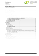
DC/AC Inverter UNV-F User Manual Page 4 (28) Table of Contents 1A. SAFETY INSTRUCTIONS ........................................................................................................................................5 1B. ELECTRIC WASTE DISPOSAL ................................................................................................................................5 2. GENERAL INFORMATION ........................................................................................................
DC/AC Inverter UNV-F User Manual Page 5 (28) 1A. Safety Instructions Warning! Because several components of operating electrical modules are charged by dangerous voltage, the improper handling of electrical modules may be the cause of accidents involving electrocution, injury, or material damages. Operation and maintenance of electrical modules must be performed by qualified skilled personnel such as electricians in accordance with EN 50110-1 or IEC 60950.
DC/AC Inverter UNV-F User Manual Page 6 (28) 2. General Information Inverters of the series UNV-F convert input side DC voltage to a stable sinusoidal output voltage. The inverters are available for delivery with an output power of 2.5, 3.3 and 5.0 kVA per module. Several units can be switched in parallel operation to increase the system output power. The UNV-F is a hot-pluggable module with rear side connectors. Only the communication wire (CAN-Bus) is connected at the front.
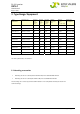
DC/AC Inverter UNV-F User Manual Page 7 (28) 3. Type Range/Equipment Type designation Material code Nominal Inputvoltage (VDC) Nominal Input current (ADC) Nominal Outputvoltage (VAC) Output frequency (Hz) Outputpower (VA @ cosφ =0.8) Dimensions W/H/D (mm) UNV48-2.5F 500-025-511.00 48 47.3 230 50/60 2500 483/133/360 UNV60-2.5F 500-025-611.00 60 37.9 230 50/60 2500 483/133/360 UNV110-2.5F 500-025-711.00 108 20.4 230 50/60 2500 483/133/360 UNV48-3.3F 500-033-511.00 48 62.
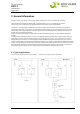
DC/AC Inverter UNV-F User Manual Page 8 (28) 3.2 Front View/Operation Elements Digital displays LED indicators Two CAN-Bus connectors Ventilation grid UP/DOWN keys ON/OFF switch (Input/output fuse) All operating elements are arranged at the front side of the module. The UNV-F, 2.5 and 3.3kVA are fitted with a combined input and output MCB which is used as ON/OFF switch, whereas the 5.0kVA version is fitted with a mechanical switch.
DC/AC Inverter UNV-F User Manual Page 9 (28) 3.3 Electrical Connectors 3.3.1 Electrical Connector X1 for UNV-F 2.5 – 3.3kVA, UNV60-5.0F and UNV110-5.
DC/AC Inverter UNV-F User Manual Page 10 (28) 3.3.2 Electrical Connector X1 for UNV48-5.
DC/AC Inverter UNV-F User Manual Page 11 (28) 3.3.3 CAN-Bus connectors CAN1 & CAN2 The UNV-F is fitted with two CAN-Bus connectors at the front side (socket outlet RJ11, 6-pole): CA N 1 6 CAN-Bus connector (socket) Pin Signals CAN1 Signals CAN2 Designation 1 CAN_V+ DC-Supply +8...15V 2 CAN_V+ DC-Supply +8...15V 3 CAN_H Signal (high) 4 CAN_L Signal (low) 5 CAN_V- DC-Supply Ground 6 CAN_V- DC-Supply Ground 3.
DC/AC Inverter UNV-F User Manual Page 12 (28) 3.5 Communication Interface The inverter UNV-F is equipped with a serial data interface according to CAN (= Controller Area Network) – specification. Via CAN-Bus, several devices in a system or parallel connection can be controlled and monitored by a central unit which is integrated into the static transfer switch unit UNB.
DC/AC Inverter UNV-F User Manual Page 13 (28) For the electrical connection of DC input and AC output the backside panel connector is to be used. The DC input is protected against wrong polarity (unit does not switch on). The UNV-F with output power of 2.5 and 3.3kVA are fitted with an output side MCB fusing at the front panel combined with an input side MCB, whereas the 5kVA version is fitted with a mechanical switch. That means that the 5kVA version must be fused with external fuses.
DC/AC Inverter UNV-F User Manual Page 14 (28) 4.3 LED Indications The following functions are indicated with front side LEDs: LED Colour Meaning green Inverter is switched on and operates green Inverter output voltage okay* red Input voltage high* red Input voltage low* red Output current to high; short circuit or overload at the output red 1.) Lights continuously: Overheating of the inverter by overload. 2.
DC/AC Inverter UNV-F User Manual Page 15 (28) 4.4 Internal Monitoring Monitored values Criteria Function Vi<: The device automatically switches off with an adjustable delay time**. It switches on if the input voltage is in the correct range. The switch-on voltage is adjustable*.
DC/AC Inverter UNV-F User Manual Page 16 (28) 4.5 Adjustment of the standard and threshold values The adjustment takes place with up/down keys located at the front panel of the inverter while the displays indicate the actual values.
DC/AC Inverter UNV-F User Manual Page 17 (28) 4.5.1 Diagram “Standard display during operation/display of input and output parameters” The continuation of the diagram is on the next page! ©2009. ELTEK VALERE DEUTSCHLAND GmbH. UM_UNVF_ E_R2.
DC/AC Inverter UNV-F User Manual Page 18 (28) Continuation of the previous page: By pressing both keys short-time at the position “” (Hardware reset) the device switches off and restarts. ©2009. ELTEK VALERE DEUTSCHLAND GmbH. UM_UNVF_ E_R2.
DC/AC Inverter UNV-F User Manual Page 19 (28) 4.5.2 Diagram “Adjustment mode” For switching to the adjustment mode shortly press both keys together at any position within the display of input and output parameters (except for the position “hardware reset”). ©2009. ELTEK VALERE DEUTSCHLAND GmbH. UM_UNVF_ E_R2.
DC/AC Inverter UNV-F User Manual Page 20 (28) You can leave the adjustment mode by pressing both keys for approximately three seconds. ©2009. ELTEK VALERE DEUTSCHLAND GmbH. UM_UNVF_ E_R2.
DC/AC Inverter UNV-F User Manual Page 21 (28) 4.5.3 Table “Adjustable Parameters” Following table shows the standard values (factory set), adjustment ranges and steps: Display1 Designation Factory setting Range Step 230 [VAC] 200...255 0,25 [V] * 207 [VAC] 180...230 1,0 [V] 253 [VAC] 230...
DC/AC Inverter UNV-F User Manual Page 22 (28) 5. Maintenance In general, the inverter is maintenance-free. A yearly inspection with following checks is recommended: Correct fan operation Mechanical inspection Removal of dust and dirt, especially on radiator surfaces Check for internal dust or humidity Attention! Dust combined with dew or water may influence the internal electronic circuits. Dust inside the unit can be blown out with dry compressed air.
DC/AC Inverter UNV-F User Manual Page 23 (28) 6.2 Error indication on the displays Switch-off (shutdown of the module) caused by error is indicated on the displays. Example: Upper display: SHd = Shutdown Lower display: Error number (example „129“) Possible single error numbers are listed in the table below: Error number (decimal number) 1 2 4 8 16 32 64 128 Meaning Io> or Vi> Vi< or fan error Vo not ok (e.g.
DC/AC Inverter UNV-F User Manual Page 24 (28) The following display indications are exceptions: At shutdown due to short circuit or overload the displays indicate the following: Upper display: SHd = Shutdown Lower display: ovL = short circuit/overload An intended shutdown via CAN-Bus by static bypass switch UNB is indicated as follows: Upper display: OFF (shutdown) Lower display: CAn (via CAN-Bus) ©2009. ELTEK VALERE DEUTSCHLAND GmbH. UM_UNVF_ E_R2.
DC/AC Inverter UNV-F User Manual Page 25 (28) 7. Technical Specifications Type range UNV-2.5F UNV-3.3F Article code See section 3, table “Type range” UNV-5.
DC/AC Inverter UNV-F User Manual Page 26 (28) Audible noise < 45dB (A) Mechanical Construction 19’’- compatible rack, full width, rear side connectors Electrical connectors Input/output and signals : HAN K 4/8 at the rear side; CAN 1 + 2 at the front side Cooling Speed-controlled fan with over temperature monitoring Type of enclosure IP20 (front panel) Dimensions (W/H/D) [mm] Minimum installation depth [mm] Weight 483/133/360 483/133/360 483/133/440 440 ex. 19’’ frame 440 ex.
DC/AC Inverter UNV-F User Manual Page 27 (28) 7.1 Dimensional drawings UNV-2.5F/UNV-3.3F: UNV-5.0F: ©2009. ELTEK VALERE DEUTSCHLAND GmbH. UM_UNVF_ E_R2.
Supplier: FAX Email Internet ELTEK VALERE DEUTSCHLAND GmbH GB Industrial Schillerstraße 16 D-32052 Herford + 49 (0) 5221 1708-210 + 49 (0) 5221 1708-222 Info.industrial@eltekvalere.com http://www.eltekvalere.com 2009. ELTEK VALERE DEUTSCHLAND GmbH. All rights reserved.