THEIA™ HE-t String Inverter ~ 2.0 - 4.4 kWAC, 600 VDC INSTALLATION GUIDE www.eltekvalere.
Information in this document is subject to change without notice and does not represent a commitment on the part of Eltek Valere. No part of this document may be reproduced or transmitted in any form or by any means — electronic or mechanical, including photocopying and recording — for any purpose without the explicit written permission of Eltek Valere. Copyright ©: Eltek Valere, 2011 357115.
Contents 1. Product Overview ......................................................................................................................... 4 1.1. Symbols Used ........................................................................................................ 4 1.2. Product Label......................................................................................................... 4 1.3. Unpacking and Inspection .............................................................................
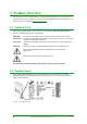
1. Product Overview This Installation Guide contains all the necessary install information to connect and start up the THEIA HE-t inverter. The inverter must be used in compliance with the THEIA HE-t User Guide, which is to be found at www.eltekvalere.com. 1.1. Symbols Used The warning symbols used in this Installation Guide highlight important information on how to avoid hazards to persons and equipment.
Table 1.2.
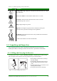
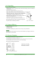
1.3.2. Unpacking Unpack the inverter as follows: • Place the box in position, with the top clearly visible and according to the arrow marking on the packaging. • Cut the seal, and open the box. • Remove the upper part of the foam packing material. • Take out the Installation Guide and the envelope with the extra product label. • Both sides of the inverter case are narrowed in order to get a better grip on the inverter.
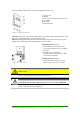
The front surface of the inverter consists of an upper and a lower cover. 1. Upper cover 2. Display 3. Lower cover; customer connection area 4. AC output 5. DC input 6. Network input Figure 1.3.4: Inverter structure The upper cover may only be removed by Eltek Valere authorized personnel.
2. Installation Installation of the THEIA HE-t inverter shall be performed by qualified installers only, who have knowledge about the local and national electrical regulations in force. DANGER: Only qualified persons may install the inverter! Only persons who are qualified to install high voltage electrical equipment and are familiar with the electrical regulations applicable to the installation site may install the inverter.
2.2. Mechanical Installation Observe the following instructions when mounting and installing the THEIA HE-t inverter on a suitable site. This is crucial to maintaining the efficiency of the inverter! WARNING: Ensure a suitable mounting surface! Correct installation prevents the inverter from falling from the wall. The mounting surface must be suitable for the weight (20-22 kg / 44-49 lbs.) and temperature (90° C / 194° F) of the inverter.
2.2.1. Wall Bracket Depending on the mounting surface, different mounting methods may be required to secure the wall bracket. The system installer is responsible for selecting the correct type and number of fixings suitable to support the weight on the mounting surface. The bracket is designed to withstand 80 kg / 176.4 lbs. D1. 232.5 mm/9.2 inches D2. 232.5 mm/9.2 inches D3. 75 mm/2.95 inches D4. 75 mm/2.95 inches 1. Carrier slots for the inverter 2. Steering slots for the inverter 3.
• Ensure that the inverter is correctly mounted, and tighten the lock clip with one screw into the inverter and one into the string box (if present). • Recommended torque is 1.0 Nm / 0.74 ft-lbf. 2.3. Electrical Installation Correct electrical connection is critical for achieving a safe, long-term and reliable operation of the entire PV system.
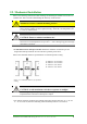
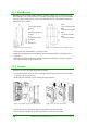
2.3.1.1. Stringbox with DC Fuse Holders and DC Switch 1. CAN bus terminal 2. Ethernet connection 3. Internal DC terminal blocks 4. DC ground terminal 5. Stringbox with fuse holders and optional DC switch 6. AC terminal block Figure 2.3.1: Stringbox with DC fuse holders and DC switch 2.3.1.2. Stringbox with DC switch and no DC Fuse Holders 1. CAN bus terminal 2. Ethernet connection 3. Internal DC terminal blocks 4. DC ground terminal 5. Stringbox with no fuse holders and DC switch 6.
2.3.2. Grounding Appropriate grounding of the entire PV system limits voltage surges, gives a common reference point for the conductive parts and facilitates the operation of the overcurrent devices. The THEIA HE-t inverters meet all relevant safety requirements and include internal surge protection. DANGER: Ensure correct grounding of the inverter and the PV array! Grounding must be carried out by qualified persons only and comply with local and national electrical regulations. 1.
2.3.3. DC Side (PV) Connections A PV string consists of a certain number of PV modules connected in series, which in turn can be connected in parallel and attached to the inverter. DANGER: Disconnect the PV array before starting DC side connections! Charged DC terminals pose a risk of serious injury or death as the PV array can supply up to 600 VDC to the inverter when exposed to sunlight.
There are three different configurations of the string box options: 1.Stringbox with DC fuse holders and DC switch 2.Stringbox with DC fuse holders and no DC switch 3.Stringbox with DC switch and no DC fuse holders 1. Stringbox with DC Fuse Holders and DC Switch The stringbox can be equipped with DC fuse holders, DC switch and plug-in connectors or cable glands. P1, P2, P3: Positive connectors N1, N2, N3: Negative connectors Figure 2.3.
2. Stringbox with DC Fuse Holders and no DC Switch The stringbox can be equipped with DC fuse holders and plug-in connectors or cable glands and a blanking plug instead of the DC switch. A DC switch must be installed separately by authorized personnel in compliance with the relevant national electrical regulations. P1, P2, P3: Positive connectors N1, N2, N3: Negative connectors BP: Blanking Plug Figure 2.3.
3. Stringbox with DC Switch and no DC Fuse Holders This option is a stringbox equipped with DC switch and plug-in connectors or cable glands, but there are no DC fuse holders. P1, P2, P3: Positive connectors N1, N2, N3: Negative connectors Figure 2.3.10: Optional DC connectors and DC switch **P1, **P2, **P3: Terminals labeled Ungrounded **N1, **N2, **N3: Terminals labeled Grounded **N4: Grounding terminal **P4: Ungrounded terminal **N5: Terminal for the grounding strap DS: DC Switch Figure 2.3.
2.3.3.2. No Stringbox: Connector Panel The connector panel is equipped with plug-in connectors or cable glands. A DC switch must be installed separately by authorized personnel in compliance with the relevant national electrical regulations. N1, N2, N3: Negative connectors P1, P2, P3: Positive connectors Figure 2.3.12: Connector panel with optional DC connectors P1’, P2’, P3’: Terminals labeled +POS (Positive) N1’, N2’, N3’: Terminals labeled –NEG (Negative) G1: DC ground terminal (See 2.3.2.
2.3.3.3. Connection Procedures • The DC conductors connecting the PV array to the inverter must each have a minimum rating of 600Vdc at all given operating temperatures. • The DC conductor cables must be sized for correct temperature rating and sunlight resistance. Use copper wire with a maximum cross-section area of between 6 to16 mm2 / 10 to 6 AWG and temperature rating 90° C /194° F for all connections.
2.3.3.4. Jumper Position for the System Grounding Setup The jumper above the - NEG terminal in the customer connection area monitors the arrangement of the DC connection according to the grounding setup. When delivered, the jumper is positioned for an ungrounded string. Depending on the requirements from the module manufacturer, the jumper must be pulled up and positioned correctly to match the grounding of the DC conductors. In case of discrepancy a message will appear in the display: “Fuse fault”.
2.3.4.1. Connection Procedures 1. AC terminal block: • GND: Ground terminal • N: Neutral terminal (TN/TT) or Phase terminal (IT) • L: Phase terminal 2. Cable gland Figure 2.3.14: Customer connection area with AC terminals • The AC conductors must be sized for the correct temperature and sunlight resistance. Use copper wire with a maximum cross-section area of 16 mm2 / 6 AWG. Ensure compliance with the relevant national electrical regulations! • The AC conductor resistance should be minimized.
2.3.5.1. Connection Procedures 1. CAN bus terminal 2. Ethernet connector 3. Network cable gland Figure 2.3.16: Customer connection area with network terminals NOTICE If multiple inverters are connected together, all inverters must be connected to the CAN bus before Start Up to benefit from single installation setup. • Ethernet: Use CAT5 or better, with size 0.21 mm2 /24 AWG, with a maximum length of 100 m. • CAN: Use a cable size 0.13 mm2 / 26 AWG, with a maximum length of 100 m.
2.3.5.2. Jumper Position for Termination Resistance With multiple inverters connected, the jumper located behind the CAN bus terminal activates the termination resistance when the pins are short-circuited, which minimizes signal reflections in the cables and avoids interference. • Single inverter: The two pins must be short-circuited (Default). • Multiple inverters connected: The master-slave configuration requires short-circuited pins on the first inverter and on the last inverter in the linked series.
2.5. Checks before Start Up Check that the bracket and the inverter are correctly mounted and secured. Check that all terminals are correctly torqued, and that all connectors and cable glands are correctly tightened and sealed. Verify that the PV open-circuit voltage, VOC, is below the limit of 600 VDC, and that the polarity is correct. Verify that the conductors on the AC side are correctly connected to the AC terminal block.
3. Start Up A minimum available voltage of 230 VDC and a power of >7 WDC is required before the inverter starts feeding power to the grid. AC side • Turn ON the AC circuit breaker(s). DC side • Turn ON the DC switch(es). 3.1. Initial Start When the inverter is started for the first time, an installation menu is automatically displayed to enable the configuration of certain critical values and operational settings. 3.1.1.
3.1.3. Function keys The function keys have the following uses: Table 3.1.1: Function keys Symbol Function Symbol Function Up: Scroll up / increase value Right: Navigate one page or value right Down: Scroll down / decrease value Enter: Select option / go to next level Left: Navigate one page or value left Cancel: Stop operation / back to previous menu item • The selected item is always highlighted in yellow. • A registered touch of a button causes a “click” sound to be heard. 3.1.3.
2. Date Adjustment DD.MM.YYYY Enter – Call up the date adjustment fields Up – Increase present digit Down - Decrease present digit Right – Select next digit Left – Select previous digit Enter – Confirm Left – Back Right – Next Enter – Confirm 3. Time Adjustment HH.
5a. Country Settings Enter – The question “Change country settings?” appears on the screen Left – Cancel Right –Ok Enter – Confirm 5b. Country Settings Enter – Call up the list of countries Up or Down – Select the country of the actual installation site Enter – Confirm Left – Back Right –Next Enter – Confirm NOTICE An installation timer ensures that the country settings can be changed within the initial 5 hours of feeding power into the grid after installation.
6. Screen Timeout Enter – Call up the digits Default – Screen backlight OFF after 60 sec Up – Increase present digit Down – Decrease present digit Left – Select previous digit Right – Select next digit Left – Back Right – Next Enter – Confirm NOTICE The smallest value to be set is 30 sec, and the highest is 99 sec. Setting the value to 0 disables the screen timeout and leaves the screen backlight ON. 7. Customer Name Enter – Call up the keyboard The keyboard enables the typing of a customer name.
• Enter must be pressed until the wanted letter/number/symbol is shown. • It is possible to navigate between the characters by using the Up arrow to set the marker into the text window, then using Left and Right to navigate between the characters. • There is a maximum space for 19 symbols in the text window.
10. Message 2 Enter – Call up the keyboard This message field is to help distinguish and identify specific inverters in a larger PV plant, or for any other information. Left – Back Right – Next Enter – Confirm 11. Owner Password Enter – Call up the digits Default: 0003.
3.2. Self Test for Italy The Self Test function is only valid for Italy. It tests the inverters’ grid monitoring function of voltage and frequency, and takes approximately 2 minutes. The Self-Test can only be activated when: • The installation procedure is executed • The country configuration is set to Italy • The inverter is in Running/Derating Mode.
4. Maintenance and Disposal Regular inspection of the PV system is an important safety precaution to ensure trouble-free operation of the entire PV plant and the THEIA HE-t inverters. Eltek Valere is committed to its policy of environmental responsibility, and therefore appeals to end users who are disposing of inverters to follow local environmental legislation and to seek safe and responsible means of disposal. 4.1.
5.
Installation Guide THEIA HE-t String Inverters 357115.033, Issue 2.
www.eltekvalere.