
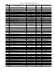
Specifications

90
Heating, ventilation and air conditioning (HVAC) and other
building equipment being controlled by ComfortLink™, PICs,
or Comfort Controller Devices have the inherent ability to
‘talk’ on a common communications bus or network. The
configuration of the communications bus with 2 or more
ComfortLink, PICs, or Comfort Controller-controlled pieces of
equipment is referred to as a Carrier Comfort Network (CCN)
system. The CCN communications bus conveys commands,
data, and alarms between all elements of the system. Any sys-
tem element connected to the bus may communicate with any
other system element, regardless of their physical locations.
The communications bus consists of a field-supplied, shielded,
3-conductor cable connected in daisy-chain fashion. The PICs,
Comfort Controllers, and other network devices (such as
TELink) can be added at any time to the network.
The main human interface with the CCN system is the
ComfortWORKS® software. The ComfortWORKS software
is installed on an IBM PC compatible computer that allows it
to connect to the communications bus and ‘talk’ directly with
any equipment connected to the network. An operator working
with ComfortWORKS software can command, monitor,
configure, or modify any portion of the system. More than one
computer with ComfortWORKS software can be used. The
computer with ComfortWORKS software, in conjunction with
optional network products, can generate a wide variety of
managerial reports which reflect the operational characteristics
of one or more buildings.
To take further advantage of the network, accessory or
optional control options modules that perform specialized
functions can be added to the communications bus at any time
to enhance the CCN system’s capabilities. Each control options
module consists of a standard hardware module with special
purpose algorithms and communications software that provide
an advanced control function for the entire CCN system or a
designated portion of the system. Data collection, remote
communications, demand limiting, and tenant billing are a few
examples of the network capabilities available to give the
building owner increased system performance and superior
building management capabilities.
Zoned systems meet the zone temperature control needs for
many commercial applications. These systems utilize a micro-
electronic thermostat as a basis for individual zone control and
typically build multiple-zone systems with constant volume
(CV) or variable-air volume (VAV) units. Zoned systems can
provide complete control of heating and cooling equipment
and zone dampers in many types of HVAC (heating, ventila-
tion and air conditioning) systems.
Digital Air Volume (DAV) Linkage — The A series
Carrier rooftop units with ComfortLinkmayalsohaveacom-
munication linkage with the VAV terminal units in a particular
application. This linkage is called the DAV linkage. In order for
this linkage to be possible, the individual VAV air terminals
must be equipped with Carrier PIC controls and the air termi-
nals must be linked by a Terminal System Manager (TSM).
The TSM acts as the communication link between the VAV air
terminal PICs and the rooftop unit. When the TSM is fully
programmed and begins communication, the rooftop control
begins using information from the TSM for rooftop unit
control operation. This is automatic, and does not require a
configuration change to the standard rooftop unit controls.
START-UP
Unit Preparation —
Check that unit has been installed in
accordance with the installation instructions and applicable
codes.
Unit Setup — Make sure that the economizer hood has
been installed and that the outdoor filters are properly installed.
Internal Wiring — Ensure that all electrical connections
in the control box are tightened as required. If the unit has
staged gas heat make sure that the LAT sensors have been
routed to the supply ducts as required.
Accessory Installation — Check to make sure that all
accessories including space thermostats and sensors have been
installed and wired as required by the instructions and unit
wiring diagrams.
Crankcase Heaters — Crankcase heaters are energized
as long as there is power to the unit, except when the compres-
sors are running.
Evaporator Fan — Fan belt and fixed pulleys are factory-
installed. See Tables 42-65 for fan performance and motor
limitations data. Remove tape from fan pulley, and be sure that
fans rotate in the proper direction. See Table 66 for motor limi-
tations. See Table 67 for air quantity limits. Static pressure drop
for power exhaust is negligible. To alter fan performance, see
Evaporator Fan Performance Adjustment section on page 104.
Controls — Use the following steps for the controls:
1. Set any control configurations that are required (field-
installed accessories, etc.). The unit is factory configured
for all appropriate factory-installed options.
2. Enter unit set points. The unit is shipped with the set point
default values. If a different set point is required use the
Scroll Marquee, Navigator or Service Tool to change the
configuration valves.
3. If the internal unit schedules are going to be used config-
ure the Occupancy schedule.
4. Verify that the control time periods programmed meet
current requirements.
5. Start unit using Service Test mode to verify operation of
all major components.
6. If the unit is a VAV unit make sure to configure the VFD
static pressure set point using the display. To checkout the
VFD use the VFD instructions shipped with the unit.
Gas Heat — Verify gas pressure before turning on gas heat
as follows:
1. Turn off field-supplied manual gas stop, located external
to the unit.
2. Connect pressure gages to supply gas tap, located at field
supplied manual shutoff valves.
3. Connect pressure gages to manifold pressure tap on unit
gas valve.
4. Supply gas pressure must not exceed 13.5 in. wg. Check
pressure at field-supplied shut-off valve.
5. Turn on manual gas stop and initiate a heating demand.
Jumper R to W1 in the control box to initiate heat.
6. Use the Service Test procedure to verify heat operation.
7. After the unit has run for several minutes, verify that
incoming pressure is 6.0 in. wg or greater and that the
manifold pressure is 3.5 in wg. If manifold pressure must
be adjusted refer to Gas Valve Adjustment section.
IMPORTANT: Do not attempt to start unit, even
momentarily, until all items on the Start-Up Checklist
(in installation instructions) and the following steps
have been completed.
IMPORTANT: Unit power must be on for 24 hrs prior
to start-up of compressors. Otherwise damage to com-
pressors may result.