
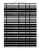
Specifications
89
The unit will first determine the mode of operation. If the
unit has been configured for space temperature demand, then
the control will determine (based on the configurable set
points) if the unit should be in the heat mode, vent mode, or
cooling mode. If the unit is configured for return air tempera-
ture control, then it will start the fan and monitor the return air
temperature against the configurable set point to determine if
the unit should be in cooling, venting, or heating mode.
If the control is connected to a ComfortID™ system, the
room terminals are equipped with microprocessor controls that
give commands to the base module. If linkage is active then
control module will replace local ComfortLink™ set points
and occupancy data with linkage supplied data.
If temperature compensated start is active then the control
will bring on the unit in advance to pre-cool or pre-heat the
space. If the unit is configured to use a pre-purge cycle then the
control will start the unit in vent mode based on a pre-start time
interval. If an IAQ sensor is being used and the low IAQ
control point is satisfied then the mode will be terminated.
If cooling mode is required, then the ComfortLink control
will control to the leaving air temperature set point. If an
economizer is present and the changeover control allows the
economizer to be used, then the control will first attempt to
control to the leaving-air temperature using free cooling. If this
cannot satisfy the load, then additional compressor stages will
be turned on to maintain the leaving air temperature. When
both compressors and economizers are being used, the control
will use the economizer dampers to maintain better control of
the leaving air and to prevent high compressor cycling. If the
economizer cannot be used, then the economizer will be set
to the minimum vent position. When using compressors, the
leaving-air temperature will be used to sequence to compres-
sors on and off using a PID control loop.
When operating in cooling, the control will also monitor the
supply duct pressure and send a 4 to 20 mA signal to the
factory-supplied VFD to control the speed of the fan and the
delivered CFM. If the unit is on a Linkage system, the control
also supports static pressure reset based on the needs of the
zones.
If the space temperature sensor (SPT), return air tempera-
ture sensor (RAT), or linkage demand requires that the unit be
in heating, then the control will energize the electric heat or gas
heat (if present) to warm the space. In this mode, the control
will energize the heat interlock relay which opens to the heat-
ing position. For linkage systems, the interlock relay connec-
tion is not required. Heating will continue until the mode selec-
tion sensor is satisfied.
Gas Heat Units (48A) — The gas heat units incorporate
2 (on sizes 020-050) or 3 (on size 060) separate systems to pro-
vide gas heat. Each system incorporates its own induced-draft
motor, Integrated Gas Control (IGC) board, 2 stage gas valve,
manifold, and safeties. On 2-stage gas heat control, the systems
operate in parallel. For example, when there is a call for first
stage heat, both induced-draft motors operate, both gas valves
are energized, and both IGC boards initiate spark. On a staged
gas heat option the individual gas stages will be controlled to
provide up to 11 stages of gas heat capacity.
All of the gas heating control is performed through the IGC
boards (located in the heating section). The MBB module on
2-stage units and the optional SCB board on staged gas heat
units only initiate and terminate heating operation and monitor
the status of the requirements for indoor fan operation. The fan
will be controlled directly by the MBB board, but when config-
ured for intermittent fan operation, the IGC IFO output will
initiate indoor fan operation.
For units with 2 stage gas heat control, the MBB is powered
by 24 VAC. When the thermostat or room sensor calls for heat-
ing as determined by the MBB, the MBB will close heating
relays and send power to W on each of the IGC boards (2 on
sizes 020-050 and 3 on size 060). An LED on the IGC board
will be on during normal operation.
A check is made to ensure that the rollout switches and limit
switches are closed and the induced-draft motors are not
running. The induced-draft motors are then energized, and
when speed is proven with the Hall Effect sensor on the motor,
the ignition activation period begins. The burners will ignite
within 5 seconds.
When ignition occurs, the IGC board will continue to moni-
tor the condition of the rollout and limit switches, the Hall
Effect sensor, and the flame sensor. If the unit is controlled
through a room thermostat set for fan auto., 45 seconds after
ignition occurs, the indoor-fan motor will be energized and the
outdoor-air dampers will open to their minimum position. If for
some reason the over temperature limit opens prior to the start
of the indoor fan blower, on the next attempt, the 45-second
delay will be shortened to 5 seconds less than the time from
initiation of heat to when the limit tripped. Gas will not be
interrupted to the burners and heating will continue. Once
modified, the fan on delay will not change back to 45 seconds
unless power is reset to the control.
If the unit is controlled through a room sensor, the indoor
fan will be operating in the occupied mode and the outdoor-air
dampers will be in the minimum position. If the unit is con-
trolled with a room sensor in the unoccupied mode, the indoor
fan will be energized through the IGC board with a 45-second
delay and the outside-air dampers will move to the minimum
unoccupied set point. When additional heat is required, the sec-
ond stage MBB output relay closes and initiates power to the
second stage of all main gas valves in all sections.
When the demand is satisfied, MBB heat output relays will
open and the gas valves close interrupting the flow of gas to the
main burners. If the call for stage 1 heat lasted less than
1 minute, the heating cycle will not terminate until 1 minute
after W1 became active. If the unit is configured for intermit-
tent fan, then the indoor-fan motor will continue to operate for
an additional 45 seconds then stop and the outdoor-air dampers
will close. If the over-temperature limit opens after the indoor
motor is stopped within 10 minutes of W1 becoming inactive,
on the next cycle the time will be extended by 15 seconds. The
maximum delay is 3 minutes. Once modified, the fan off delay
will not change back to 45 seconds unless power is reset to the
control.
If the unit is equipped with the optional staged gas heat
control option, then each board and each stage of capacity will
be control separately to provide up to 11 stages of gas heat
capacity as determine by the average leaving air temperature.
The first two stages will be controlled by the MBB and the next
4 stages will be controlled by the SCB. By changing the combi-
nations of the stages, up to 11 stages will be used.
CCN Network System — The A series units with the
ComfortLink control can operate either in a stand-alone mode
or they can be interfaced with the Carrier Comfort Network
(CCN), Building Supervisor, or Service Tool. When being
installed in network applications, the unit is connected to the
CCN communications bus with field-installed cable.
Other equipment can also be installed on the CCN by fitting
the equipment with a Comfort Controller Device. The Comfort
Controller Device has a standard processor module (PSIO) but
is field-programmed for use with other HVAC components. A
typical configuration is shown in Fig. 20.