
Specifications
87
3. The space temperature set points and the supply air set
points are configured under the SETPOINTS menu. The
heating and cooling set points must be configured. See
the General Heating and Cooling Control section for fur-
ther description on these configurations. Configure the
following set points:
OHSP Occupied Heat Set Point
OCSP Occupied Cool Set Point
UHSP Unoccupied Heat Set Point
UCSP Unoccupied Cool Set Point
GAP Heat-Cool Set Point Gap
SA.SP Supply Air Set Point
SA.HT Heating Supply Air Set Point
V.C.ON VAV Occupied Cool On Set Point
V.C.OF VAV Occupied Cool Off Delta
4. To program time schedules, set SCH.N=1 under the
TIMECLOCK menu to configure the control to use local
schedules.
5. Under the TIMECLOCK-SCH.L submenu, enter the
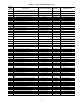
desired schedule or schedules. See Table 20 for further
descriptions of these configurations.
6. Under the TIMECLOCK menu, the following schedules
and overrides should be configured:
OTL Override time limit
OVR.S SPT override enabled?
OVR.T T58 override enabled?
7. Under the CONFIGURATION menu, the Supply Duct
Static (SP.SP) set point should be configured.
8. If Supply air reset is desired, under the
CONFIGURATION-RST submenu, the following set
points should be configured:
RST.T Supply Air Reset Configuration
RTIO Reset Ratio
R.LIM Reset Limit
9. See the Economizer Options section below for additional
economizer option configurations.
10. See the Exhaust Options section below for additional
exhaust option configurations.
Multi-Stage Constant Volume Units with
Mechanical Thermostat — To configure the unit, per-
form the following:
1. Under the CONFIGURATION-UNIT submenu, set
CTL.Tto3(TSTATMULTI).
2. Remove jumpers from R-W2 and W2-W1.
3. Under the SETPOINTS menu, set the following
configurations:
HI.SA Supply Air Set Point High
LO.SA Supply Air Set Point Low
4. See the Economizer Options section below for additional
economizer option configurations.
5. See the Exhaust Options section below for additional
exhaust option configurations.
Multi-Stage Constant Volume Units with Space
Sensor —
To configure the unit, perform the following:
1. Under the CONFIGURATION-UNIT submenu, set
CTL.T to 5 (SPT MULTI).
2. Under the CONFIGURATION-CMF.D submenu, the
heating and cooling set points must be configured. Con-
figure the following set points:
LH.ON Demand Level Lo Heat On
HH.ON Demand Level Hi Heat On
LH.OF Demand Level Lo Heat Off
LC.ON Demand Level Lo Cool On
HC.ON Demand Level Hi Cool On
LC.OF Demand Level Lo Cool Off
CT.LV Cool Trend Demand Level
HT.LV Heat Trend Demand Level
CT.TM Cool Trend Time
HT.TM Heat Trend Time
3. Ensure jumpers are installed between R-W2 and W2-W1.
4. Under the SETPOINTS menu, the following configura-
tions should be set:
HI.SA Supply Air Set Point High
LO.SA Supply Air Set Point Low
5. Under the SETPOINTS submenu, the heating and cool-
ing set points must be configured:
OHSP Occupied Heat Set Point
OCSP Occupied Cool Set Point
UHSP Unoccupied Heat Set Point
UCSP Unoccupied Cool Set Point
GAP Heat-Cool Set Point Gap
6. Under the CONFIGURATION-OPTS submenu, enable
the space sensor by setting SPT.S to enable.
7. Under the CONFIGURATION-UNIT submenu, set
FAM.M to 1 for continuous fan or 0 for automatic fan.
8. To program time schedules, set SCH.N=1 under the
TIMECLOCK menu to configure the control to use local
schedules.
9. Under the TIMECLOCK-SCH.L submenu, enter the
desired schedule or schedules. See Table 20 for further
descriptions of these configurations.
10. See the Economizer Options section below for additional
economizer option configurations.
11. See the Exhaust Options section below for additional
exhaust option configurations.
Economizer Options — Under the CONFIGURATION-
ECON submenu, the following set points should be configured:
EC.EQ Economizer Installed
E.CGO Economizer Changeover Select
MIN.P Economizer Minimum Position
OAT.L High OAT Lockout Temperature
OA.EC Enthalpy Curve Select (only used for out-
door enthalpy changeover)
OA.DL OA Dewpoint Limit (only when using out-
side air humidity sensor)
OEN.C Outdoor Enthalpy Compare Value (only
used with custom curve control)
EC.CB Economizer Temperature Deadband
If the unit is going to be used with IAQ control then additional
configurations will be required for the IAQ control. See the
section on Demand Ventilation.
Exhaust Options — The following exhaust options
should be configured.
TWO-STAGE EXHAUST OPTION — For two-stage ex-
haust, under the CONFIGURATION-ECON submenu,
configure the following:
PWRX Power Exhaust option should be set to 1
PWRM Power Exhaust motors should be set to 1
(4 motors) for the 020-050 units and 2
(6 motors) for the 060 unit
PE1.P Power Exhaust On 1 Set Point
PE2.P Power Exhaust On 2 Set Point
MODULATING EXHAUST OPTION — For modulating ex-
haust, the unit must have the ECB2 and the building pressure
sensor installed. To configure, set the following variables in the
CONFIGURATION-ECON submenu:
PWRX Power Exhaust option should be set to 1