
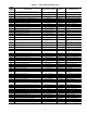
Specifications

86
occurs when the Supply Air temperature sensor (SAT) is out-
side the range –40 to 240 F (–40 to 116 C). This alert resets au-
tomatically. The cause of the alarm is usually a faulty ther-
mistor, a shorted or open thermistor caused by a wiring error, or
a loose connection.
Alert and Alarm Codes 701, 702, 703, 704 (Supply air
Temperature Thermistor Failure) — Alerts 701, 702, and 703
are for failures of the staged gas heat supply air sensors 1, 2,
and 3. Alarm 704 is an Alarm of all 3 sensors have failed. This
alarm occurs when the sensor(s) are outside the range –40 to
240 F (–40 to 116 C). This alert resets automatically. When in
alert staged gas heat will be stopped.
QUICK SETUP
The following section will provide a quick user guide to set-
ting up and configuring the A series units with ComfortLink™
controls.
Two-Stage Constant Volume Units with
Mechanical Thermostat — To configure the unit, per-
form the following:
1. The type of control is configured under the
CONFIGURATION-UNIT submenu. Set CTL.T to 3
(TSTAT MULTI) or 4 (TSTAT 2 STAGE). Carrier rec-
ommends that TSTAT MULTI be used as the unit will
have more than 2 stages of cooling capacity.
2. Remove jumpers from R-W2 and W2-W1.
3. See Economizer Options section on page 87 for addition-
al economizer option configurations.
4. See Exhaust Options section on page 87 for additional
exhaust option configurations.
Two-Stage Constant Volume Units with Space
Sensor —
To configure the unit, perform the following:
1. The type of control is configured under
CONFIGURATION-UNIT submenu. Set CTL.T to 5
(SPT MULTI) or 6 (SPT 2 STAGE). Carrier recommends
that SPT MULTI be used as the unit will have more stag-
es of capacity that with SPT 2 STAGE.
2. Under CONFIGURATION-OPTS submenu, enable the
space sensor by setting SPT.S to enable.
3. The space temperature set points are configured under the
SETPOINTS menu. The heating and cooling set points
must be configured. See the General Heating and Cooling
Control section for further description on these configura-
tions. Configure the following set points:
OHSP Occupied Heat Set Point
OCSP Occupied Cool Set Point
UHSP Unoccupied Heat Set Point
UCSP Unoccupied Cool Set Point
GAP Heat-Cool Set Point Gap
4. The degrees of demand from the space temperature set
points are configured under the CONFIGURATION-
CMF.D Submenu. See the General Heating and Cooling
Run Control section for further description on these con-
figurations. Configure the following set points:
LH.ON Demand Level Lo Heat On
HH.ON Demand Level Hi Heat On
LH.OF Demand Level Lo Heat Off
LC.ON Demand Level Lo Cool On
HC.ON Demand Level Hi Cool On
LC.OF Demand Level Lo Cool Off
CT.LV Cool Trend Demand Level
HT.LV Heat Trend Demand Level
CT.TM Cool Trend Time
HT.TM Heat Trend Time
5. Ensure jumpers are installed between R-W2 and W2-W1.
6. Under the CONFIGURATION-UNIT submenu, set
FAN.M to 1 for continuous fan or 0 for automatic fan.
Most building codes now require continuous fan for
ventilation.
7. To program local time schedules, set SCH.N=1 under the
TIMECLOCK menu to configure the control to use local
schedules.
8. Under the TIMECLOCK-SCH.L submenu, enter the
desired schedule. See Table 20 for further descriptions of
these configurations.
9. Under the TIMECLOCK menu, the following schedules
and overrides should be configured:
OTL Override time limit
OVR.S SPT override enabled?
OVR.T T58 override enabled?
10. See Economizer Options section on page 87 for addition-
al economizer option configurations.
11. See Exhaust Options section on page 87 for additional
exhaust option configurations.
Variable Air Volume Units Using Return Air
Sensor —
To configure the unit, perform the following:
1. The type of control is configured under the
CONFIGURATION-UNIT submenu. Set CTL.T to 1
(VAV-RAT).
2. The space temperature set points and the supply air set
points are configured under the SETPOINTS menu. The
heating and cooling set points must be configured. See
the General Heating and Cooling Run Control section for
further description on these configurations. Configure the
following set points:
OHSP Occupied Heat Set Point
OCSP Occupied Cool Set Point
UHSP Unoccupied Heat Set Point
UCSP Unoccupied Cool Set Point
GAP Heat-Cool Set Point Gap
SA.SP Supply Air Set Point
SA.HT Heating Supply Air Set Point
V.C.ON VAV Occupied Cool On Set Point
V.C.OF VAV Occupied Cool Off Delta
3. To program time schedules, set SCH.N=1 under the
TIMECLOCK menu to configure the control to use local
schedules.
4. Under the TIMECLOCK-SCH.L submenu, enter the
desired schedule or schedules. See Table 20 for further
descriptions of these configurations.
5. Under the SETPOINTS menu, the Supply Duct Static
(SP.SP) set point should be configured.
6. If Supply Air Reset is desired, under the
CONFIGURATION-RST submenu, the following set
points should be configured:
RST.T Supply Air Reset Configuration
RTIO Reset Ratio
R.LIM Reset Limit
7. See the Economizer Options section on page 87 for addi-
tional economizer option configurations.
8. See the Exhaust Options section on page 87 for additional
exhaust option configurations.
Variable Air Volume Units Using Space Tem-
perature Sensor —
To configure the unit, perform the
following:
1. The type of control is configured under the
CONFIGURATION-UNIT submenu. Set CTL.T to 2
(VAV-SPT).
2. Under the CONFIGURATION-OPTS submenu, enable
the space sensor by setting SPT.S to enable.