
Specifications
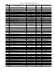

82
DIAGNOSTIC ALARM CODES AND POSSIBLE
CAUSES
Alert Codes 51, 52, 55 and 56 (Compressor Safety)
—Alert
codes 51, 52, 55, and 56 are for compressors A1, A2, B1, and
B2 respectively. These alerts occur when the Current Sensor
(CS) does not detect compressor current during compressor
operation. When this occurs, the control turns off the compres-
sor and logs a strike for the respective circuit. These alerts reset
automatically.
The possible causes are:
• High-pressure switch (HPS) open. The HPS-pressure
switch is wired in series with compressor relays on the
MBB. If the high-pressure switch opens during compressor
operation, the compressor stops, and the CS no longer
detects current, causing the control to activate this alert.
• Compressor internal overload protection is open. The inter-
nal overloads are used on the Scroll Tech compressors
(black) and smaller Maneurop compressors used on the 020,
025, 027, 030, 035 units and 040 A1, A2 compressors.
• Internal compressor temperature sensor trip. The large
Maneurop compressors (blue) used on the 040 B1, B2, 050,
and 060 units have an internal temperature sensor.
• Circuit Breaker trip. The compressors are protected from
short circuit by a breaker in the control box. On the 020-035
and 040 A1, A2 units there is one breaker per two compres-
sors and on the 040 B1, B2 and 050, 060 compressors there
is one breaker per compressor because there is not internal
overloads.
• Wiring error. A wiring error might not allow the compressor
to start.
To check out alerts 51, 52, 55 and 56:
1. Turn on the compressor in question using Service Test
mode. If the compressor does not start, then most likely
the problem is one of the following: HPS open, open
internal protection, circuit breaker trip, incorrect safety
wiring, or incorrect compressor wiring.
2. If the compressor does start verify it is rotating in the cor-
rect direction.
3. If the compressor starts, verify that the indoor and
outdoor fans are operating properly.
4. If the CS is always detecting current, then verify that the
compressor is on. If the compressor is on, check the
contactor and the relay on the MBB. If the compressor is
off and there is no current, verify CS wiring and replace if
necessary.
5. Return to Normal mode and observe compressor opera-
tion to verify that compressor current sensor is working
and condenser fans are energized after compressor starts.
Alert Codes 51, 52, 55 and 56 (Current Detected After Turnoff)
— Alert codes 51, 52, 55, and 56 are for compressors A1, A2,
B1, B2 respectively. These alerts occur when the Current Sen-
sor, (CS) detects current when the compressor should be off.
When this occurs, the control turns off the compressor and logs
a strike for the respective circuit. Use the Scrolling Marquee to
reset the alert.
The possible causes are:
• Welded contactor.
• Frozen compressor relay on MBB.
To check out alerts 51, 52, 55, and 56
1. Place the unit in Service Test Mode. All compressors
should be Off.
2. Verify that there is not 24V at the contactor coil. If there is
24V at the contactor, check relay on MBB and wiring.
3. Check for welded contactor.
4. Verify CS wiring.
5. Return to Normal mode and observe compressor opera-
tion to verify that compressor current sensor is working
and condenser fans are energized after compressor starts.
Alert Codes 64, and 65 (Condensing Temp. Failure)
—Alert
codes 64, and 65 are for circuits A and B respectively. These
alerts occur when the saturated condensing temperatures
(SCT.A and SCT.B) are outside the range –40 to 240 F (–40 to
116 C). When this occurs, the control uses the outdoor temper-
ature (OAT) to control the outdoor fans. The control will
default to control based on the OAT sensor and will turn on
OFC.B when the ambient is above 65 F and off when the ambi-
ent is below 50 F.
If the SCT and OAT sensors have all failed then the control
should turn on OFC.B when compressors are on.
The cause of the alert is usually a faulty thermistor, a shorted
or open thermistor caused by a wiring error, or a loose connection.
Alert Code 72 (Remote Setpoint/Rest Input Failure)
— If
the unit is configured to use the Remote Supply Air Set Point/
Reset 4 to 20 mA (RM.SP) and the sensor reading is less than
2 mA or greater than 22 mA then the alert will occur. When this
occurs the control will default to the internal set points. The
sensor is connected to the optional CEM module. For this sensor
to be used, the EDT Reset Input (EDT.R) must be set to enable.
This is located in the CONFIGURATION-OPTS submenu.
Alert Code 73 (Outside Air Temp. Failure)
— This alert oc-
curs when the outside air temperature sensor (OAT) is outside
the range –40 to 240 F (–40 to 116 C). This alert resets auto-
matically. The cause of the alert is usually a faulty thermistor, a
shorted or open thermistor caused by a wiring error, or a loose
connection.
Alert Code 74 (Space Temp. Failure)
— This alert occurs
when the space temperature sensor (SPT) is outside the range
–40 to 240 F (–40 to 116 C). This alert will only occur if
the unit is configured to use a space temperature sensor.
Configuration is done through the Unit Control Type (CTL.T)
configuration, which is located in the CONFIGURATION-
UNIT submenu. The unit will shut down if this alert occurs
while in Space Sensor mode. This alert resets automatically.
The cause of the alert is usually a faulty thermistor in the T55,
T56, or T58 device, a shorted or open thermistor caused by a
wiring error, or a loose connection.
Alert Code 75 (Return Air Temp. Failure)
— This alert oc-
curs when the return air temperature sensor (RAT) is outside
the range –40 to 240 F (–40 to 116 C). The RAT is standard on
all units and is located in the return section near the auxiliary
control box. This alert resets automatically. The cause of the
alert is usually a faulty thermistor, a shorted or open thermistor
caused by a wiring error, or a loose connection.
Alert Code 76 (Outside Air Relative Humidity Sensor Fail-
ure) — This alert occurs when the outside air humidity sensor
(OA.RH) has a reading less than 2 mA or greater than 22 mA.
The OA.RH sensor is located in the economizer hood and is
used for control of the economizer. The sensor is a loop pow-
ered 4 to 20 mA sensor. This alert resets automatically. The
cause of the alert is usually a faulty sensor, a shorted or open
sensor caused by a wiring error, or a loose connection. The unit
must be configured to use the sensor through the Outside
AirRHSensor(ORHS)setting,whichislocatedinthe
CONFIGURATION (OPTS) submenu.
Alert Code 78 (Return Air Relative Humidity Sensor Fail-
ure) — This alert occurs when the return air humidity sensor
(RA.RH) has a reading less than 2 mA or greater than 22 mA.
The RA.RH sensor is located in the return air section near the
auxiliary control box. The sensor is a loop powered 4 to 20 mA
sensor. This alert resets automatically. The cause of the alert is
usually a faulty sensor, a shorted or open sensor caused by
a wiring error, or a loose connection. The unit must be
IMPORTANT: Prolonged operation in the wrong direc-
tion can damage the compressor. Correct rotation can be
verified by a gage set and looking for a differential pres-
sure rise on start-up.