
Specifications
79
IAQ DISC. INPUT NORMALLY (IAQ.L) — This is located
in the CONFIGURATION-SW.LG submenu and is used to
configure the normally open/closed status of the switch.
PRESS. SWITCH NORMALLY (PRS.L) — This is located
in the CONFIGURATION-SW.LG submenu and is used to
configure the normally open/closed status of the switch.
SMOKE PURGE SW. NORMALLY (PRG.L) — This is lo-
cated in the CONFIGURATION-SW.LG submenu and is used
to configure the normally open/closed status of the switch.
Fan Status Monitoring — The fan status switch is an
option that allows for the monitoring of a discrete switch,
which trips above a differential pressure drop across the supply
fan. For units with VFDs not controlled by third parties, it is
possible to measure duct pressure rise directly, which would
remove the need for this option.
There is a configuration, which selects the type of fan status
monitoring (IF.M) to be performed. Possible configurations
are: NONE — No switch or monitoring, SWITCH — Use of
the fan status switch, DELTA PRESS — Monitoring of the
supply duct pressure.
As the unit will always protect itself, there is also a configu-
ration which will allow for the fan status to alarm and shut
down the unit or simply send out an alert. This configuration is
called Fan Fail Shuts Down Unit (IS.FS) and is located in the
CONFIGURATION-UNIT submenu. If enabled, it will shut
down the unit if a failure is detected.
To allow for flexibility in choosing third party fan status
switches, a configuration is provided that reverses the logic
state read based on whether the switch is normally open (NO)
or normally closed (NC). This variable is called Fan Status SW.
Normally: (SFS.L) and is located in the CONFIGURATION-
SW.LG submenu.
Dirty Filter Switch — The unit can be equipped with a
factory or field installed accessory dirty filter switch. The
switch is located in the auxiliary control box.
If no dirty filter switch is installed, the switch input is de-
signed to read clean all the time. Therefore, the dirty filter rou-
tine runs all the time.
The dirty filter routine waits for 2 minutes of fan operation
before the dirty filter switch is monitored.
After 2 minutes, if the dirty filter switch reads “bad” for 2
continuous minutes, the alert is generated.
Recovery from this alert is done through a clearing of all
alarms or after cleaning the filter.
Remote Control Switch Input — The remote switch
input located on the ECB-1 board and connected to TB6 termi-
nals 1 and 3. The switch can be used for several remote control
functions.
The switch is configured using the Remote Switch Config
(RMT.C), which is located in the CONFIGURATION-OPTS
submenu. The configurations are:
• NONE — Switch will not be used.
• OCCUPANCY — Switch will be used to signal occupied/
unoccupied modes.
• START STOP — Switch will be configured for start-stop
control of the unit.
The control also allows for the configuration of the normally
open/closed status of the switch. This is configured using Re-
mote Switch Normally (PMI.L) variable, which is located in the
CONFIGURATION-SW.LG submenu.
Control Level Forcing — If any of the following
points are forced with a priority level of 7, the software clears
the force from the point if it has not been written to or forced
again within the timeout periods defined below:
Time out periods:
OAT 30 minutes Outside Air Temperature
OAQ 30 minutes Outside Air Quality
OARH 30 minutes Outside Air Relative Humidity
SPT 3 minutes Space Temperature
SPRESET 30 minutes Static Pressure Reset
Test Mode — The control can test the outputs. This can be
used during start-up and also during diagnostic investigations.
There are four major test mode categories: Independent,
Fans, Cooling, and Heating. Within each category there are sub-
menu items and functions. These are summarized in Table 13
and the Service Test Menu.
This routine is enabled using the SERVICE-TEST sub-
menu. The user will be required to enter the password.
Alarms and Alerts — There are a variety of different
alerts and alarms in the system.
P — Pre-Alert: Part of the unit is temporarily down. The
alarm is not broadcast on the CCN Network. The alarm relay is
not energized. After an allowable number of retries, if the
function does not recover, the pre-alert will be upgraded to an
alert or an alarm.
T — Alert: Part of the unit is down, but the unit is still
partially able to provide cooling or heating.
A — Alarm: The unit is down and is unable to provide
cooling or heating.
All alarms are displayed with a code of AXXX where the A
is the category of alarm (Pre-Alert, Alert, or Alarm) and XXX
is the number.
The response of the control system to various alerts and
alarms depends on the seriousness of the particular alert or
alarm. In the mildest case, an alert does not affect the operation
of the unit in any manner. An alert can also cause a “strike.” A
“striking” alert will cause the circuit to shut down for 15 min-
utes. This feature reduces the likelihood of false alarms causing
a properly working system to be shutdown incorrectly. If three
strikes occur before the circuit has an opportunity to show that
it can function properly, the circuit will strike out, causing the
shutdown alarm for that particular circuit. Once activated, the
shutdown alarm can only be cleared via an alarm reset.
Circuits with strikes are given an opportunity to reset their
strike counter to zero. As discussed above, a strike typically
causes the circuit to shut down. Fifteen minutes later, that
circuit will once again be allowed to run. If the circuit is able to
run for 1 minute, its replacement circuit will be allowed to shut
down (if not required to run to satisfy requested stages). How-
ever, the “troubled” circuit must run continuously for 5 minutes
with no detectable problems before the strike counter is reset to
zero.
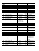
All the alarms and alerts are summarized in Table 41.
Operators with CCN networks might not want to be notified
of “striking” alerts until a circuit has been shut down because
of three alerts. If the operator sets A.NOW (Alarm Now) to
NO, alerts will not be announced until a circuit is permanently
shut down. This implies that alarm will not be broadcast on the
CCN network or listed on the display until a permanent shut
down alarm occurs.
The status of A.NOW is ignored during Service Test mode
because it is presumed that the service technician will want to
be notified of any alerts or alarms immediately. So it will not
confuse a monitor center, the words “SERVICE TEST” are
inserted into every alarm message while the unit is operating in
Service Test Mode.