
Specifications

77
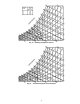
The rooftop unit has the design static pressure set point
programmed into the CCN control. This is the maximum set
point that could ever be achieved under any condition. To
simplify the installation and commissioning process for the
field, this system control is designed so that the installer only
needs to enter a maximum duct design pressure or maximum
equipment pressure, whichever is less. There is no longer a
need to calculate the worst case pressure drop at design condi-
tions and then hope that some intermediate condition does
not require a higher supply static pressure to meet the load
conditions. For example, a system design requirement may
be 1.2 in. wg, the equipment may be capable of providing
3.0 in. wg and the supply duct is designed for 5.0 in. wg. In this
case, the installer could enter 3.0 in. wg as the supply static
pressure set point and allow the air terminal system to dynami-
cally adjust the supply duct static pressure set point as required.
The system will determine the actual set point required deliver-
ing the required airflow at every terminal under the current
load conditions. It will always be the lowest value under the
given conditions, and as the conditions and airflow set point at
each terminal change throughout the operating period, and so
will the equipment static pressure set point.
The CCN system must have access to a CCN variable
(SPRESET which is part of the equipment controller). In the
algorithm for static pressure control, the SPRESET value is
always subtracted from the configured static pressure set point
by the equipment controller. The SPRESET variable is always
checked to be a positive value or zero only (negative values are
clamped to zero). The result of the subtraction of the SPRESET
variable from the configured set point is limited so that it
cannot be less than zero.
The result is that the system will dynamically determine
the required duct static pressure based on the actual load
conditions currently in the space. It eliminates the need to
calculate the design supply static pressure set point (although
some may still want to do it anyway). It also saves the energy
that is the difference between the design static pressure set
point and the required static pressure (multiplied by the
airflow). Normally, the VAV system operates at the design
static pressure set point all the time, however, a typical VAV
system operates at design conditions less than 2% of the time.
A significant saving in fan horsepower can be achieved utiliz-
ing static pressure reset.
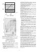
Building Pressure Control — The control will sup-
port control of the building pressure using power exhaust fans.
The type of control is configured using the PWRX variable.
The types are as follows:
PWRX = 0, No building pressure control
PWRX = 1, Building pressure control based on economizer
position
PWRX = 2, Modulating building pressure control based on
building pressure sensor
When PWRX is 1 or 2, there are either four or six power ex-
haust motors, attached to three relays. See Table 39.
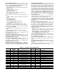
Table 39 — Power Exhaust Fan Relays
For a PWRX configuration of 1 the control will use the con-
figurable PE Stage 1 Econo Position (PE1.P) and PE Stage 2
Econo Position (PE2.P) damper positions to operate two stages
of power exhaust. For a 4-motor system the first stage of
exhaust will energize PE-B and the second stage will energize
all PE relays.
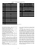
For a PWRX of 2 the control will use a building pressure
sensor to control the sequencing of the power exhaust fans. A
PID control loop will be used. This can be used on both VAV
and CV units. The fan stages as shown in Table 40 will be used
to control the measure building pressure to the configurable
Building Pressure Set Point (BP.SP).
The control has 3 modes of running the fans for building
pressure control mode. Option 2 should be used.
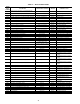
Table 40 — Modulating Power Exhaust
Staging Sequence
SIZES 020-050
SIZE060
BUILDING PRESSURE SET POINT (BP.SP) — This is the
building pressure set point. It is located in the SETPOINT-
BP.SP submenu.
POWER EXHAUST TYPE (PWRX) — This is the type of
power exhaust and has the following options. It is located in the
CONFIGURATION-ECON submenu.
• MODULATING — This will use the building pressure
sensor.
• 2 STAGE — This will control the dampers based on the two
configurable damper position set point.
• NONE — No building pressure control will be used. This
should be set to NONE for barometric relief dampers.
POWER EXHAUST MOTORS (PWRM) — This configures
the number of power exhaust fan motors and has the following
options.
• 4 MOTORS — This should be used on all units except size
060.
• 6 MOTORS — This should be used on size 060 units.
PE STAGE 1 ECONO POSITION (PE1.P) — This is the
damper position that will be used to turn on the first stage of
fans when using 2 stage control.
PE STAGE 2 ECONO POSITION (PE2.P) — This is the
damper position that will be used to turn on the second stage of
fans when using 2 stage control.
MODULATING PE ALG SELECT (BP.SL) — This is a selec-
tion for different power exhaust control routines. Only routine
2 should be used.
BUILDING PRESSURE SENSOR (BP.S) — This is used to
enable and disable the use of a building pressure sensor. It must
be enabled for the modulating control to work. It can also be
enable for the other modes where monitoring of the building
pressure is desired.
UNIT
SIZE
SETTING
PE_A
RELAY
PE_B
RELAY
PE_C
RELAY
020-050
PWRM = 1
(4 motors)
1 Motor 2 Motors 1 Motor
060
PWRM = 2
(6 motors)
1 Motor 2 Motors 3 Motors
PWRM = 4PE_APE_BPE_C
Stage 0 OFF OFF OFF
Stage 1 ON OFF OFF
Stage 2 OFF ON OFF
Stage 3 ON ON OFF
Stage 4 ON ON ON
PWRM = 6PE_APE_BPE_C
Stage 0 OFF OFF OFF
Stage 1 ON OFF OFF
Stage 2 OFF ON OFF
Stage 3 ON ON OFF
Stage 4 ON OFF ON
Stage 5 OFF ON ON
Stage 6 ON ON ON