
Specifications

76
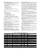
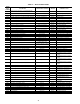
Table 38 — VFD (E3 Inverter) Configurations
*These settings differ from the Toshiba defaults and are required for Carrier applications.
DIFF. GAIN SF VFD (SP.KD) — This is the differential gain
for the static pressure control PID control loop.
INTEGRAL GAIN SF VFD (SP.KI) — This is the integral
gain for the static pressure PID control loop.
SYSTEM /GAIN SF VFD (SP.K) — This is the overall sys-
tem gain for the static pressure PID control loop.
VFD PID TIME (SECONDS) (SP.DT) — This is the time
factor for the static pressure control PID loop.
DUCT PRESS SENSOR HI END (SPHL) — This is the
maximum static pressure that the sensor will measure when the
signal is 20 mA.
DUCT PRESS SENSOR LO END (SPLL) — This is the
minimum static pressure that the sensor will measure when the
signal is 4 mA.
Under most operating conditions the control PID factors
will not require any adjustment and the factory defaults should
be used. If a condition is detected where the VFD speed is
fluctuating up and down from the static pressure and it over-
shoots and undershoots the set point, then use the System Gain
SF VFD (SP.K) factor. Decrease the factor a small amount to
reduce the responsiveness of the control loop and increase it to
increase the responsiveness of the control loop. Do not change
the other factors without consulting with Carrier Application
department.
Static Pressure Reset — The ComfortLink™ con-
trols supports the use of static pressure reset. For static pressure
reset to occur, the unit must be part of a CCN system with
access to CCN reset variable and the Linkage Master Terminal
System Logic.
The Linkage Master terminal monitors the primary air
damper position of all the terminals in the system (done
through LINKAGE with the new ComfortID™ air terminals).
It then calculates the amount of supply static pressure reduction
necessary to cause the most open damper in the system to open
more than the minimum value (60%) but not more than the
maximum value (90% or negligible static pressure drop). This
is a dynamic calculation, which occurs every two minutes
whenever the system is operating. The calculation ensures that
the supply static pressure is always enough to supply the
required airflow at the worst case terminal but never more than
necessary, so that the primary air dampers do not have to oper-
ate with an excessive pressure drop (more than required to
maintain the airflow set point of each individual terminal in the
system). As the system operates, if the most open damper
opens more than 90%, the system recalculates the pressure
reduction variable and the value is reduced. Because the reset
value is subtracted from the controlling set point at the equip-
ment, the pressure set point increases and the primary air
dampers close a little (to less than 90%). If the most open
damper closes to less than 60%, the system recalculates the
pressure reduction variable and the value is increased. This
results in a decrease in the controlling set point at the equip-
ment, which causes the primary air dampers to open a little
more (to greater than 60%).
SetP SETUP PARAMETERS GR.SF FREQ. SETTING PARAMETERS
ACC1 60.0 sec Fsor 60 Hz
DEC1 60.0 sec Gr.Pn PANEL CONTROL PARAMETERS
UL 60.0 Hz Fr 0*
LL 0 Hz FGr.St TERMINAL SELECTION PARAMETERS
lulu 1 lt 1
P3 20% lt0 0
F-P3 0.0 Hz lt1 56
P4 100% lt2 13
F-P4 60 Hz lt3 3
tHr1 — lt4 10
StC1 0 GGr.Pr PROTECTION PARAMETERS
StL1 110% UuC 1*
OLN 1 UuCt 2
tYP 5 ArSt 3
Gr.F FUNDAMENTAL PARAMETERS Gr.Ut UTILITY PARAMETERS
FH 60Hz* Cnod 4*
UL 60Hz Fnod 4*
pt 2 bLPn 1*
GR.Fb FEEDBACK PARAMETERS
FbP1 0*
Fbln 2
GP 0.3
Gl 2 sec
GA 0
GFS 0 80
P1LL 10
PuL 1
PuU1 10
PuLL 10