
Specifications

75
Pre-Occupancy Purge — The control has the option
for a pre-occupancy purge to clear the space prior to occupan-
cy. The feature is enabled by the PRG.E variable which is locat-
ed in the CONFIGURATION-IAQ submenu.
The IAQ Purge will operate under the following conditions:
• PRG.E is enabled
• the unit is in the unoccupied state
• Current Time is valid
• Next Occupied Time is valid
• time is within two hours of the next occupied period
• time is within the purge duration
If all of the above conditions are met, the following logic is
used:
If (OAT >= NTLO and OAT <= OCSP and economizer is
available)
Then PURGEMP = 100%
Else if (OAT < NTLO)
Then PURGEMP = LT.MP (default = 10%)
Else PURGEMP = HT.MP (default = 35%)
If PURGEMP > 0% then IAQ Purge Mode is enabled.
If this mode is enabled the indoor fan and heat interlock re-
lay (VAV) will be energized and the economizer's minimum
position is set to PURGEMP.
PURGEMP = 0% when IAQ purge mode is not active (en-
abled).
The following configurations are used for this option.
IAQ PURGE (PRG.E) — This is used to enable IAQ
pre-occupancy purge. This can be configured in the
CONFIGURATION-IAQ submenu.
IAQ PURGE LO TEMP MIN POS (PG.LT) — This is used
to configure a low limit for damper position to be used
during the purge mode This can be configured in the
CONFIGURATION-IAQ submenu.
IAQ PURGE HI TEMP MIN POS (PG.HT) — This is used
to configure a maximum position for the dampers to be
used during the purge cycle. This can be configured in the
CONFIGURATION-IAQ submenu.
NIGHT TIME LOCKOUT TEMP (NT.LO) — Night time
lockout temperature below which the purge cycle will be dis-
abled. This is configured in the SETPOINTS-COOL submenu.
Static Pressure Control — The control supports the
use of an VFD for fan speed control and static pressure control.
All VAV units are equipped with an VFD for the supply fan.
The speed of the fan will be controlled directly by the
ComfortLink™ Control. A duct static pressure sensor is locat-
ed in the auxiliary control box The signal from the pressure
sensor will be measure by the ECB2 board and will be used in
a PID control routine in the ComfortLink Controls that will
output a 4 to 20 mA signal to the VFD. The static pressure con-
trol set point (SP.SP) is in the SETPOINTS-SP.SP submenu.
Other configurable variables that apply to static pressure con-
trol are listed below. These can be set in the CONFIGURA-
TION-SVFD submenu.
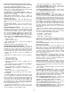
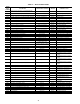
The VFD also has configuration settings which are set at the
VFD. These settings are shown in Tables 37 and 38.
The supply fan relay is not turned off when controlling a
VFD. This is to prevent condensation on the VFD and associat-
ed electronics. The speed will be set to 0% when the unit is in
the Off Mode.
DUCT STATIC PRESSURE SENSOR (SP.S) — This en-
ables the use of a supply duct static pressure sensor. This must
be enabled to use the ComfortLink control loop. If using a
third party control for the VFD then this should be disabled.
STATIC PRESSURE CONTROL (SP.C) — This is used to
configure the use of the ComfortLink for VFD control. It has
the following options:
• NONE — No direct VFD control by ComfortLink control.
This would be used if there was third-party control of the
VFD. The control of the VFD must be provided.
• VFD CONTROL — This will enable the use of the
ComfortLink VFD and static pressure control.
IDF VFD MINIMUM SPEED (SF.MN) — This is the mini-
mum speed that the VFD will turn down to. The inverter also
has a minimum speed adjustment.
IDF VFD MAXIMUM SPEED (SF.MX) — This is the max-
imum speed that the VFD can ramp up to. Usually this is set to
100%.
IDF SPEED IN FIRE MODE (SF.FS) — This is the speed
that the VFD will use during the fire modes like pressurization,
and purge.
PROP. GAIN SF VFD (SP.KP) — This is the proportional
gain for the static pressure control PID control logic.
Table 37 — VFD (S9 Inverter) Configurations
TITLE
COMMUNICATION
NUMBER
FUNCTION
DEFAULT
SETTING
CARRIER
SETTINGS
COMMENTS
CMOD 0003 Command Mode Selection 1 0 Auto Operation
FMOD 0004 Frequency Setting Mode Selection 2 0 Remote Operation
Fr 0008 Forward/Reverse Run Selection 0 1 Reverse run (required due to fan config)
ACC 0009 Acceleration Time 1 10 60
DEC 0010 Deceleration Time 1 10 60
FH 0011 Maximum Frequency 80 60
UL 0012 Upper Limit Frequency 80 60
Pt 0015 V/F Control Mode Selection 0 1 Variable torque load
F116 0116 Input Terminal Selection (S3) 8 11 Normally open E-Stop
F201 0201 VIA/II Input 1 Setting 0 20 0 Hz at 4 mA
F204 0204 V1A/II Input 2 Frequency 80 60 60 Hz at 20 mA
F300 0300 PWM Carrier Frequency 12 4
F301 0301 Auto-Restart Control Selection 0 3 Auto -restart activated
F302 0302
Regenerative Power Ride
through Control
01
Enable ride though
F303 0303 Retry Selection 0 2 Number of retrys
Sr1 0018 Pre-Set Speed 1 0 60 Fire Speed
OLN 0017 Electronic Thermal Protection 1 1=overload and stall protection