
Specifications
73
IAQ Control — The ComfortLink™ control has the capa-
bility of demand ventilation control using an IAQ sensor. The
indoor air quality (IAQ) is measured using a CO
2
sensor whose
measurements are displayed in parts per million (PPM). The
IAQ sensor can be field-installed or factory-installed in the
return duct. If IAQ must be measured directly in the space
instead of the unit return duct, a wall-mounted accessory can be
field installed. The sensor must be 4 to 20 mA and must be
include a 24-V supply. Remote sensors should be powered
from an external 24-V supply. The sensor connects to TB5
terminal 6 and 7. Be sure to leave the 182-ohm resistor in place
on terminals 6 and 7.
The unit’s indoor air quality algorithm modulates the
position of the economizer damper between two user configu-
rations depending upon the relationship between the IAQ and
the Outdoor Air Quality (OAQ). The lower of these two
positions is referred to as the Minimum IAQ Damper Position
(AQ.MP) while the higher is referred as Economizer Minimum
Position (MIN.P). The AQ.MP should be set to an economizer
position that brings in enough fresh air to remove contaminants
and CO
2
generated by sources other than people. The MIN.P
should be set to an economizer position that brings in enough
fresh air to remove contaminants and CO
2
generated by all
sources including people. The MIN.P value is the design value
for maximum occupancy.
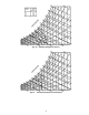
The logic that is used to control the dampers in response to
IAQ conditions is shown in Fig. 26. Refer to this figure to help
understand how the logic works. The ComfortLink control will
begin to open the damper from the AQ.MP position when the
IAQ level begins to exceed the OAQ level by a configurable
amount, which is referred to as AQ Differential Low (AQD.L).
If OAQ is not being measured, OAQ can be manually config-
ured. It should be set at around 400 to 450 ppm or measured
with a handheld sensor during the commissioning of the unit.
The OAQ reference level can be set using the OAQ Set Point
(OA.SP) which is located in the CONFIGURATION-IAQ
submenu. When the differential between IAQ and OAQ
reaches the configurable Diff. Air Quality Hi Limit (AQD.H),
then the economizer position will be MIN.P. When the
IAQ-OAQ differential is between AQD.L and AQD.H, the
control will modulate the damper between AQ.MP and MIN.P
as shown in Fig. 26. The relationship is a linear relationship but
other non-linear options can be used. The damper position will
never exceed the bounds specified by AQ.MP and MIN.P
during IAQ control. If the building is occupied and the indoor
fan is running and the differential between IAQ and OAQ is
less than AQD.L, the economizer will remain at AQ.MP. The
economizer will not close completely. The damper position
will be 0 when the fan is not running or the building is unoccu-
pied. The damper position may exceed MIN.P in order to
provide free cooling.
The ComfortLink control is configured for air quality
sensors which provide 4 mA at 0 PPM and 20 mA at
2000 PPM. If a sensor has a different range, these bounds must
be reconfigured. The values for I.4M, I.20M, O.4M, O.20M
are located in the CONFIGURATION-IAQ submenu. The
bounds represent the PPM corresponding to 4 mA and 20 mA
for IAQ and OAQ, respectively.
If OAQ exceeds the OAQ Lockout Value (OAQ.L), then
the economizer will remain at AQ.MP. The OAQ.L value can
be configured in the CONFIGURATIONS-IAQ submenu. This
is used to limit the use of outside air which outdoor air CO
2
levels are above the OAQ.L limit.
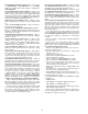
Normally a linear control of the damper vs. the IAQ control
signal can be used, but the control also supports non-linear
control. Different curves can be used based on the Diff.IAQ
Responsiveness Variable (I.CRV) which is located on the
CONFIGURATION-IAQ submenu. See Fig. 27.
The control also supports the use of external IAQ control
signals, which can be connected to TB5 terminals 6 and 7. This
will work like the IAQ sensor, except the 4 to 20 mA signal
will come from an external energy management system. At 4
mA the position of the economizer will be at the AQ.MP posi-
tion and at 20 mA the position will be at the MIN.P position.
The user will have to configure the IAQ MinPos Sensor
Config (IA.CF) to CNTL MIN POS which is located in the
CONFIGURATION-IAQ submenu.
The control also supports the use of an IAQ override switch,
which is connected to TB6 terminals 13 and 14. This option
will allow the use of an external IAQ signal to move the econo-
mizer between the AQ.MIN position and a configurable
maximum position called IAQ Econo Override Pos (OVR.P)
The user will have to configure the IAQ MinPos Sensor
Config (IA.CF) to OVERRIDE, which is located in the
CONFIGURATION-IAQ submenu.
The IAQ routine can also be configured to work with the
CCN DCV POC which requires that the IAQ MinPos Sensor
Config (IA.CF) be set to DCV.
The IAQ routine can also be configured to override the
indoor fan and turn it on. This is configured through the IAQ
4 to 20 mA fan config (IA.FN), which is located in the
CONFIGURATION-IAQ submenu.
There are a large number of configurations that can be used
with the IAQ routine. Most have been covered in the above
paragraphs, but the following will provide some additional
details and explanations.
IAQ MIN POS SENSOR CONFIG (IA.CF) — This is used
to configure the type of IAQ position control. It has the follow-
ing options:
• MIN POS POT — Used with a remote potentiometer that is
used for control of the minimum position (IQMIN). The
potentiometer must be a 10K potentiometer and will be
connected TB5 terminals 6 and 7.
• CNTL MIN POS — This is used when a remote 4 to
20 mA signal will be used for the IAQ input.
• OVERRIDE IAQ — This will be used with an IAQ over-
ride switch is used.
• DCV — This will be used with DCV control.
• NO IAQ — This configuration will indicate that no remote
IAQ minimum setting will be used and the internal software
setting will be used.
IAQ 4 TO 20 MA FAN CONFIG (IA.FN) — This configura-
tion is used to configure the control of the indoor fan. If this
option is used then the IAQ sensor must be in the space and not
in the return duct. It has the following configurations:
• NEVER — IAQ demand will never override the fan and
turn it on.
• OCCUPIED — IAQ demand will override the fan in occu-
pied mode only.
• OVERRIDE IAQ — IAQ will always override the status of
the indoor fan.
IAQ DISCRETE INPUT CONFIG (IAIC) — This configu-
ration is used to set the type of IAQ sensor. The following are
the options:
• NO IAQ — This is used to indicate that no discrete input
will be used and the standard IAQ sensor input will be used.
• DCV — This will indicate that the IAQ level will be
communicated through CCN.
• OVERRIDE IAQ — This will indicate that an IAQ
override switch will be used.