
Specifications
72
ECONOMIZER CONTROL TYPE (E.CTL) — The options
of DIG/POSITION, DIG/COMMAND, and ANALOG
CTRL are available. The control should be configured for
DIG/COMMAND.
ECONOMIZER MIN POSITION (MIN.P) — This is the
minimum position that is used for ventilation requirements dur-
ing the occupancy periods. If the unit is equipped with an IAQ
sensor, then the dampers may be modulated below this position
if the IAQ CO
2
levels are low. The MIN.P position will then be
used for the maximum IAQ ventilation position.
HIGH OAT LOCKOUT TEMP (OAT.L) — This is a config-
urable temperature above which the economizer will be locked
out.
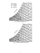
A, B, C, D CURVE SELECT (OA.EC) — These are the select-
able curves as shown in Fig. 24.
OUTDOOR AIR DEWPOINT TEMP LIMIT (OA.DL) —
This is a configurable maximum dewpoint temperature above
which the economizer will be disabled. It can be used with any
of the changeover controls.
OUTDOOR ENTH COMPARE VALVE (OEN.C) — This is
a CCN broadcast enthalpy valve that can be used for enthalpy
changeover control.
UNOCC FREE COOL CONFIG (UFC.C) — This is used to
configure the unoccupied free cooling economizer control.
If set to 1, then free cooling will be available during the unoc-
cupied period. If set to 2, then free cooling will start UFC.T
minutes before the occupied period.
UNOCC FREE COOL TIME (UFC.T) — This is the config-
urable time, which will be used for unoccupied free cooling
prior to start-up.
ENABLE ECONOMIZER TRIM (TRM.E) — This will be
used to enable the economizer trim routine to close the damp-
ers during periods which both the economizer mode and
compressors are being used. The purpose is to limit compressor
cycles and to provide better temperature control.
ECONOMIZER TEMP DEADBAND (EC.CB) — This is an
adjustable temperature deadband within which the economizer
will not be adjusted to maintain the leaving-air temperature.
REMOTE ECONOMIZER SWITCH (E.ENA) — In addi-
tion to the normal economizer control, the ComfortLink™ also
supports the use of a remote economizer enable control where
the economizer will be enabled and disabled from a remote
switch input. The same switch can also be configured
to control a 2-position economizer. The switch is connected
to TB6, terminals 1 and 2. The use of the switch must be
configured using the Economizer Switch Configuration
(ECO.S), which is located in the CONFIGURATION-OPTS
submenu. The ECO.S can be configured for the following:
0=NONE, 1=ECON ENABLE, 2=POSITION OVERRIDE.
When configured for Econ Enable, the closure of the switch
will indicate that the economizer can be used for free cooling.
The control will then use the economizer control routine which
controls to the high or low demand supply air set point.
When the switch is configured for Position Override it will
act as a 2-position damper. When the switch is closed and the
unit is in the occupied mode, the position will be set to the
economizer min position (MIN.P). When the switch is closed,
the dampers will open to the full open position.
RETURN AIR RH SENSOR (R.RH.S) — This is located in
the CONFIGURATION-OPTS submenu and is used to enable
and disable the use of the return air humidity sensor.
OUTSIDE AIR RH SENSOR (O.RH.S) — This is located in
the CONFIGURATION-OPTS submenu and is used to enable
and disable the use of the outside air humidity sensor.
ECONOMIZER SWITCH NORMALLY (EC.SL) — This is
located in the CONFIGURATION-SW.LG submenu and is
used to configure the normally open and closed status of the
switch.
UNOCCUPIED ECONOMIZER FREE COOLING — Unoc-
cupied Economizer Free Cooling is used to start the indoor fan/
supply fan when the outside temperature is low to pre-cool the
space with outside air. This is done to delay the need for me-
chanical cooling when the system enters the occupied period.
Once the space has been sufficiently cooled during this cycle,
the fan will be stopped.
To use this option the user must configure the Unocc Free
Cooling Configuration Variable (UFC.C) which can be found
in the CONFIGURATION-ECON submenu. The following are
the options: 0 = disabled, 1= all the time, 2= x time before
occupied.
If set to 1, then free cooling will be used anytime during the
unoccupied period.
If set to 2, then free cooling will be started for a config-
urable time before the next occupied period. The configuration
variable is Unocc. Free Cooling time (UFC.T) and is located in
the CONFIGURATION-ECON submenu.
There are some qualifications that must occur for the unoc-
cupied free cooling to be used.
• The UFC.C (unoccupied economizer free cooling option)
must be set to 1 or 2.
• Unit is in the unoccupied state.
• Temperature Compensated Start Mode is not active.
• Unit configured for economizer.
• Not in a cooling mode (HVACMODE not in cooling).
• Not in a heating mode (HVACMODE not in heating).
• Space temp reading available, which means the control
must be using an SPT sensor and can not be using an
electro-mechanical 2 stage thermostat.
• Outside air temperature reading is available (OAT sensor
status good).
• Economizer active except for the fact that the fan has not
been on for 30 seconds (internal timing).
• OAT > NTLO (nighttime lockout temperature) with 1° F.
If all of the above conditions are met, unoccupied free cool-
ingroutineisallowedtobeused.
The Night Time Free Cooling Set point (NT.SP) is calculat-
ed as follows:
NTSP = OCSP
The Night Free Cooling Mode shall be started when:
SPT>(NTSP+2)andSPT>(OAT+8)
The Night Time Free Cooling Mode shall be stopped when:
SPT < NTSP or SPT < (OAT + 3)
When the Unoccupied Economizer Free Cooling mode is
active, the supply air fan is turned on and economizer damper
is modulated to control to the set point.