
Specifications

70
An LED indicator is provided on the IGC to monitor opera-
tion. The IGC boards are located in the gas heat section below
the indoor fans. During normal operation the LED is continu-
ously on. Table 35 shows the error codes.
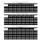
Table 35 — IGC LED Indicators
NOTES:
1. There is a 3 second pause between error code displays.
2. If more than one error code exists, all applicable error codes
will be displayed in numerical sequence.
3. Error codes on the IGC will be lost if power to the unit is
interrupted.
Economizer — The ComfortLink™ controls determine
the economizer position. The economizer is used to provide
ventilation air and also provide free cooling based on a
configurable changeover command.
The economizer damper position is controlled by a digitally
controlled actuator motor that is connected directly the dampers.
The logic that is used to control the motor is based on the
evaporator discharge temperature sensor (EDT). The demand
temperature control logic uses the high and low cool demands
for the economizer control. The set points can be configured
in the SETPOINTS-HI.SA and SETPOINTS-LO.SA submenus
using the Supply air Set Point HI (HI.SA) and Supply Air Set
Point LO (LO.SA) configurations. The HVAC mode routine
HVAVSPT2 logic will determine when the high or low set point
will be used.
The following settings in the CONFIGURATION-ECON
menu can be used to configure the operation of the economizer.
EC.EQ — ECONOMIZER INSTALLED — This is a Yes/
No configuration and indicates that there is an economizer
installed.
E.CGO — ECON CHANGEOVER SELECT — This is used
to select the type of changeover control. The types are Outdoor
dry bulb changeover control, Differential dry bulb changeover
control, Outdoor Enthalpy changeover control, Differential En-
thalpy control, and Custom Curve.
All units are equipped with an outside and return air dry
bulb temperature sensor so the unit can be configured for either
dry bulb or differential dry bulb control.
OUTDOOR DRY BULB CHANGEOVER CONTROL —
This is used when the use of the economizer will be determined
based on outside air temperature. Typically this is used in dry
climates where outdoor humidity is relatively low. All units
are shipped as standard with an outdoor air temperature
(OAT) which is located inside the economizer hood. The set
point for the outdoor air upper limit can be configured in the
CONFIGURATION-ECON submenu using the High OAT
Lockout Temp (OAT.L) setting.
DIFFERENTIAL DRY BULB CHANGEOVER CON-
TROL — This is used to compare the outdoor temperature
with the return duct temperature which then allows the
airstream with the lowest temperature to be used. All units are
shipped with an outside air (OAT) and return air temperature
sensor (RAT). The factory default configuration is differential
dry bulb changeover control. No configuration is required
other than to enable the feature using the Econ Changeover
Select (E.CGO) setting.
OUTDOOR ENTHALPY CHANGEOVER CONTROL —
This option uses the outdoor enthalpy A, B, C, or D curve to
determine the changeover. See Fig. 24 for the curves. This
option should be used in climates with higher humidity condi-
tions. Unlike most control systems that use an enthalpy switch
or enthalpy sensor, the A series units use the outdoor dry bulb
sensor and an accessory relative humidity sensor (OA.RH) to
calculate the enthalpy of the air. In addition the software has the
standard A, B, C, and D curves built into the control for use in
changeover control. The High OAT lockout temperature can
still be used in combination with the enthalpy curves.
DIFFERENTIAL ENTHALPY CONTROL — This option
compares the outdoor air enthalpy with the return air enthalpy
and uses the airstream with the lowest enthalpy. This option
should be used in climates with high humidity conditions. This
option also uses humidity sensors and dry bulb sensors to
calculate the enthalpy of the outdoor and return air. An
accessory outdoor air humidity sensor (OA.RH) and return air
humidity sensor (RA.RH) are used for this. The High OAT
lockout temperature can still be used in combination with the
differential changeover control.
CUSTOM CURVE — This is a new feature in the industry.
The custom curve feature allows for a combination of an
enthalpy/dewpoint curve and a dry bulb curve. As shown in
Fig. 25, the user can set a maximum outdoor air enthalpy curve
as one limit and then set a dry bulb curve as another limit to
create a custom curve. As enthalpy and dewpoint saturation
curves are essentially parallel, Table 36 can be used to convert
dewpoint to enthalpy.
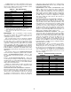
Table 36 — Dewpoint-Enthalpy Conversion
ERROR CODE LED INDICATION
Normal Operation On
Hardware Failure Off
Fan On/Off Delay Modified 1Flash
Limit Switch Fault 2 Flashes
Fame Sense Fault 3 Flashes
Five Consecutive Limit Switch Faults 4 Flashes
Ignition Lockout Fault 5 Flashes
Ignition Switch Fault 6 Flashes
Rollout Switch Fault 7 Flashes
Internal Control Fault 8 Flashes
Software Lockout 9 Flashes
DEWPOINT
(F)
ENTHALPY
(BTU/LB)
50 20.29
51 20.85
52 21.43
53 22.01
54 22.61
55 23.22
56 23.84
57 24.47
58 25.12
59 25.78
60 26.45
61 27.14
62 27.85