
Specifications

68
The first two staged gas heat outputs are located on the
MBB board and outputs 3, 4, 5, and 6 are located on the SCB
board. These outputs are used to determine the number of
stages (5 to 11) as shown in Tables 31-34.
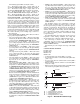
IGC Control Logic — All gas heat units are equipped
with the IGC board. This board provides control for the
ignition system for the gas heat sections. On size 020-050 units
there will be two IGC boards. On size 060 units there are three
IGC boards.
When a call for gas heat is initiated, power is sent to W on
the IGC boards. For standard 2-stage heat, all boards are wired
in parallel. For staged gas heat, each board is controlled
separately. When energized, an LED on the IGC board will
be turned on. Each board will ensure that the rollout switch
and limit switch are closed. The induced-draft motor is then
energized. When the speed of the motor is proven with the Hall
Effect Sensor on the motor, the ignition activation period
begins.
The burners ignite within 5 seconds. If the burners do not
light, there is a 22-second delay before another 5-second attempt
is made. If the burners still do not light, this sequence is repeated
for 15 minutes. After 15 minutes have elapsed and the burners
have not ignited then heating is locked out. The control will
reset when the request for W (heat) is temporarily removed.
When ignition occurs, the IGC board will continue to
monitor the condition of the rollout switch, limit switches, Hall
Effect Sensor, and the flame sensor. For 45 seconds after
ignition has occurred, the IGC will request that the indoor fan
be turned on. The IGC fan output is connected to indoor fan
input on the MBB which will indicate to the controls that the
indoor fan should be turned on (if not already on). If for some
reason the overtemperature limit switch trips prior to the start
of the indoor fan blower, on the next attempt the 45 second de-
lay will be shortened by 5 seconds. Gas will not be interrupted
to the burners and heating will continue. Once modified, the
fan delay will not change back to 45 seconds unless power is
reset to the control.
The IGC boards only control the first stage of gas heat on
each gas valve. The second stages are controlled directly from
the MBB board.
The IGC board has a minimum on-time of 1 minute. In
Modes such as Service Test where long minimum on times are
not enforced, the one-minute timer on the IGC will still be fol-
lowed and the gas will remain on for a minimum of one minute.
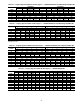
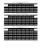
Table 30 — Staged Gas Heat
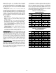
Table 31 — Staged Gas Heat Control Steps (N.HST = 1)
UNIT SIZE HEAT CAPACITY
UNIT MODEL NO.
POSITION NO. 5
N.HTR
ENTRY VALUE
N.HST
ENTRY VALUE
020-035
Low S 1 1 = 5 STAGE
High T 2 2 = 7 STAGE
040-050
Low S 1 1 = 5 STAGE
High T 1 1 = 5 STAGE
060
Low S 4 4 = 11 STAGE
High T 3 3 = 9 STAGE
STAGE
RELAY OUTPUT
CAPACITY
%
Heat 1 Heat 2 Heat 3 Heat 4 Heat 5 Heat 6
MBB-RLY8 MBB-RLY7 SCB-RLY1 SCB-RLY2 SCB-RLY3 SCB-RLY4
IGC1 MGV1 IGC2 MGV2 IGC3 MGV3
0 OFF OFF OFF OFF OFF OFF 0
1 ON OFF OFF OFF OFF OFF 37
2 ON ON OFF OFF OFF OFF 50
3 ON OFF ON OFF OFF OFF 75
4 ON ON ON OFF OFF OFF 87
5 ON ON ON ON OFF OFF 100