
Specifications

67
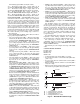
Head Pressure Control — The condenser head pres-
sure control for the 48/50A series is controlled directly by the
ComfortLink™ control. The SCT.A and SCT.B sensors, which
are connected to the condenser coils in circuit A and B, will be
used to measure the saturated condensing temperature. The
actual values saturated condensing levels can be viewed using
the TEMPERATURE-CIRC submenu. The equivalent refrig-
erant pressure can be viewed in PRESSURE-CIRC submenu
using the SCP.A and SCP.B variables. These readings will be
used to control the two condenser fan relays using the follow-
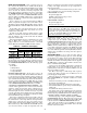
ing logic. See Table 29.
If any compressor is on, then Condenser Fan A (OFC.A)
will be energized. If the highest active circuit SCT is above
105 F then Condenser Fan B (OFC.B) will be turned on. If the
highest SCT falls below 70 F then OFC.B fan should be turned
off.
If the OAT is above 75 F, then both fan relays are turned
on until the ambient temperature drops below 73 F or the
compressors are turned off.
If either of the SCT sensors has failed, then the control
defaults to control based on the OAT sensor and turns on OFC2
when the ambient is above 65 F and off when the ambient
temperature is below 50 F.
If the SCT and OAT sensors have all failed then the control
turns on OFC2 when compressors are on. If the unit is
equipped with the accessory Motormaster® V control until
then the Motormaster Installed (S.MM) should be enabled.
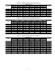
Table 29 — Condenser Fan Staging
Heating Control — The ComfortLink control controls
the optional gas or electric heat. The type of heating is selected
using the Heating Type (HT.TY) variable that can be found in
the CONFIGURATION-HEAT menu. The following options
are available:
0=NoHeat
1 = Electric Heat
2=2StageGasHeat
3 = Staged Gas Heat
HEATING WITH LINKAGE — If the unit is going to be
used with a CCN Linkage POC, then the EDT sensor will have
to relocated from the factory-installed position (entering the
fans) to the leaving ductwork position. This will allow the link-
age to determine that the unit is in the heat mode and make the
necessary terminal adjustments for CFM. This also requires
that the SAT Sensor Sense Heat configuration (LAT.M) located
in the CONFIGURATION-HEAT submenu be set to YES.
2-STAGE GAS AND ELECTRIC HEAT CONTROL — For
constant volume applications, the control uses the thermostat
demand to control the heat. If the unit is configured for use
with a conventional 2-stage thermostat, then the W1 and W2
thermostat inputs are used to control the two stages of gas heat
or electric heat. If the unit is configured for Space Temperature
Control (SPT), then the low and high heat control logic will be
used to determine the stage of capacity.
If the unit is configured for VAV operation with a return air
sensor or VAV operation with a space temperature sensor, then
the demand driven control logic with low and high demand
will be used to control the two stages of heat. The need for
heating will be determined by the HVAC heating and cooling
Mode selection logic. Both VAV-RAT and VAV-SPT start and
end a heat mode based on return air temperature. The only
difference is during unoccupied mode, when the determination
to bring on the supply fan is based on space temperature or
return air temperature.
In addition to the normal demand driven logic there are also
some overrides based on evaporator discharge temperature.
If HVACMODE = Low Heat
Request the supply fan
If EDT < 50 energize heat stages 1 and 2
Else energize heat stage 1
If HVACMODE = High Heat
Request the supply fan
Energize heat stage 1 and 2
MORNING WARMUP — Morning warmup is a subset of
heating mode. Units that have been configured for no
occupied heat (set the OCC.H variable to NO in the
CONFIGURATION-HEAT submenu) will still go into heating
when changing from unoccupied to occupied mode. If the re-
turn air temperature is below the occupied heating set point
(OHSP), then heat will be turned on until the set point is ex-
ceeded. If the temperature drops below the OHSP, then it will
be turned on again until a condition is reached where the RAT
exceeds the VAV Occupied On Set Point (B.C.ON) and then it
will be locked out until the next change from unoccupied to
occupied mode.
Staged Gas Heat — As an option, the units with gas
heat can be equipped with staged gas heat controls that will
provide from 5 to 11 stages of heat capacity. This is intended
for tempering air on CV units. Staged gas can be used on VAV
units but the minimum CV heating airflow must be supplied.
The HIR must be connected to the terminals controls to drive
them to a minimum heating CFM.
Staged gas heat (if installed) will attempt to maintain the
heating supply air set point (SA.SH) in low heat mode or
tempering mode. If the unit is in a high heat HVAC mode, all
stages of gas will be energized.
The Heat control loop is a PID design with exceptions,
overrides and clamps. Capacity rises and falls based on set
point and supply air temperature.
When the staged gas control is in Low Heat or Tempering
Mode (HVACMODE), the algorithm calculates the desired
heat capacity.
The basic factors that govern the controlling technique are:
• How fast the algorithm is run.
• The amount of proportional and derivative gain applied.
• The maximum allowed capacity change each time this algo-
rithm is run.
• Deadband hold-off range when rate is low.
The staging of the gas heat will depend on the model size
and amount of heat order. The pattern will be selected based on
the Heat Stage Type (N.HST) which has the following options:
2 STAGE, 5 STAGE, 7 STAGE, 9 STAGE, 11 STAGE.
The Heat Stage Type can be configured using the CONFIG-
URATION-HEAT submenu. When using staged gas heat, the
Heat Type (HT.TY) must be configured for Staged Heat. This
is also located in the CONFIGURATION-HEAT submenu.
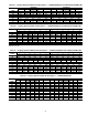
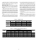
The values that should be used for N.HST are shown in
Tables 30-34. They are not field-selectable values and must
match the values in the tables.
FAN RELAY
4850A UNIT SIZE
020-035 040-050 060
OFC1
(RELAY 6)
OFM1
OFM1,
OFM2
OFM1, OFM2
OFC2
(RELAY 5)
OFM2
OFM3,
OFM4
OFM3, OFM4,
OFM5, OFM6
IMPORTANT: When gas or electric heat is used with
VAV applications, the HIR relay output must be
connected to VAV terminal controls that will drive the
terminals to an open position that provides airflow at
or above the minimum CFM for the unit. Failure to do
this will result in limit switch tripping.