
Specifications

64
balance tight control over the EDT, while concurrently
minimizing compressor cycles. The basic control variable is
called Load Factor (LOD.F). It is equal to SUM/Z, which is a
ratio of the demand for cooling over an adjustable control limit.
The LOD.F set point can be viewed in the RUN STATUS-
VIEW submenu.
The logic also includes a series of override conditions that
can cause mechanical staging to occur asynchronous to the
SUM/Z ratio. The override conditions are an integral part of the
algorithm. The PID algorithms are not generally well equipped
to handle rarely occurring conditions but are able to tightly
control the controlled point during normal operation. The over-
rides, in part, allow the control to intervene when the PID is not
able to act quickly.
The overrides are:
• Pulldown Control — limits the addition of stages when the
EDT is far from set point, but making steady progress
towards set point
• Slow Change Override — keeps sum from integrating when
the EDT is close to the set point and not changing rapidly
• Low Temperature Override — quickly removes stages
when a substantial building load suddenly is removed (as
when an auditorium vacates)
• High Temperature Override — quickly adds stages when a
substantial building load is suddenly added (as when an
auditorium fills up).
• Trim Control Override — eliminates a stage of mechanical
cooling if the economizer can make up the cooling that is to
be lost when the mechanical cooling is shut off.
Pull Down Control
— If the error from set point is above 4° F,
and the rate of change is less than –1° F per minute, then pull
down is in effect, and sum is set to 0. This keeps mechanical
cooling stages from being added when the error is very large,
but there is no load in the space. Pull down for rooftop units is
expected to rarely occur, but is included for the rare situation
when it is needed. Most likely, pull down will occur when
mechanical cooling first becomes available shortly after the
control goes into an occupied mode (after a warm unoccupied
mode).
Slow Change Override
— With a rooftop unit, the design rise
at 100% total unit capacity is generally around 30° F. For a unit
with 4 stages, each stage represents about 7.5° F of change to
EDT. If stages could reliably be cycled at very fast rates, the set
point could be maintained very precisely. Since it is not desir-
able to cycle compressors more than 6 cycles per hour, slow
change override takes care of keeping the PID under control
when “relatively” close to set point.
Normally this control logic will not require any tuning or
adjust other than to select the temperature control set points. If
there is an application where the unit may be significantly
oversized and there are indications of high compressor cycles
then the Capacity Threshold Adjust (Z.GN) can be used to
adjust the overall logic gain. Normally this is set to 1.0, but it
can be adjusted from 0.5 to 4.0. As the number is increased the
responsiveness of the logic will be slowed.
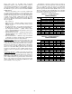
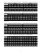
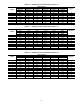
Table 23 — 2-Stage Sequence —
48/50AJ,AW020-027
*Compressor start is delay 10 seconds from other compressor.
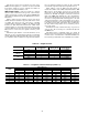
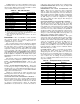
Table 24 — 2-Stage Sequence —
48/50AJ,AW030-060
*Compressor start is delay 10 seconds from other compressor.
STAGE
SEQUENCE 1 SEQUENCE 2
01 201 2
Thermostat Inputs Thermostat Inputs
Y1 OPEN CLOSED CLOSED OPEN CLOSED CLOSED
Y2 OPEN CLOSED CLOSED OPEN CLOSED CLOSED
COMP Compressor Status Compressor Status
A1 OFF ON ON OFF OFF ON
A2 OFF OFF ON OFF ON ON
B1 OFF OFF ON* OFF OFF ON*
Unit Capacity Unit Capacity
20 0% 33% 100% 0% 33% 100%
25 0% 30% 100% 0% 30% 100%
27 0% 33% 100% 0% 33% 100%
STAGE
SEQUENCE 1 SEQUENCE 2
01 201 2
Thermostat Inputs Thermostat Inputs
Y1 OPEN CLOSED CLOSED OPEN CLOSED CLOSED
Y2 OPEN CLOSED CLOSED OPEN CLOSED CLOSED
COMP Compressor Status Compressor Status
A1 OFF ON ON OFF ON* ON
A2 OFF ON* ON OFF ON ON
B1 OFF OFF ON OFF OFF ON*
B2 OFF OFF ON* OFF OFF ON
Unit Capacity Unit Capacity
30 0% 33% 100% 0% 49% 100%
35 0% 49% 100% 0% 48% 100%
40 0% 48% 100% 0% 43% 100%
50 0% 43% 100% 0% 45% 100%
60 0% 50% 100% 0% 50% 100%