
Specifications

5
SCROLLING MARQUEE — This device is the keypad in-
terface used to access the control information, read sensor
values, and test the unit. The Scrolling Marquee display is a
4-key, 4-character, 16-segment LED display as well as an
Alarm Status LED. See Fig. 14. The display is easy to operate
using 4 buttons and a group of 11 LED’s that indicate the
followingmenustructures:
• Run Status
• Service Test
• Temperatures
•Pressures
• Set points
• Inputs
• Outputs
• Configuration
• Timeclock
• Operating Modes
•Alarms
Through the Scrolling Marquee the user can access all the
inputs and outputs to check on their values and status. Because
the unit is equipped with suction pressure transducers and
discharge saturation temperature sensors it can also display
pressures typically obtained from gages. The control includes a
full alarm history, which can be accessed from the display. In
addition, through the Scrolling Marquee the user can access a
built-in test routine that can be used at start-up commission and
to diagnose operational problems with the unit. The Scrolling
Marquee is located in the main control box and is standard on
all units.
SUPPLY FAN — The 20 to 50 ton units are equipped with
two 15 x 11-in. forward-curved fans. The 60 ton units have
three 15 x 11-in. fans. They are on a common shaft and are
driven by common belt drive 3-phase motor. The fan is con-
trolled directly by the ComfortLink™ Controls.
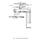
VARIABLE FREQUENCY DRIVE (VFD) — On variable
volume units, the supply fan speed is controlled by a 3-phase
VFD. The VFD is located in the fan section behind a remov-
able panel as shown in Fig. 8 and 9. The VFD speed is con-
trolled directly by the ComfortLink controls through a 4 to
20 mA signal based on a supply duct pressure sensor. The in-
verter has a display, which can be used for service diagnostics,
but setup of the building pressure and control loop factors is
done through the Scrolling Marquee display. The VFD is pow-
ered during normal operation to prevent condensation from
forming on the boards during the off mode and is stopped by
driving the speed to 0 (by sending a 0 mA signal to the VFD).
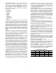
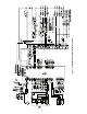
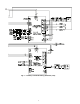
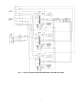
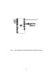
The A series units use Toshiba S9 and E3 VFDs. The inter-
face wiring for the VFDs is shown in Fig. 15 and 16. The VFD
connects through an isolation board to the 4 to 20 mA ECB2
board. Terminal designations are shown in Tables 8 and 9.
POWER EXHAUST — The units can be equipped with an
optional power exhaust system. The power exhaust fans are
forward-curved fans with direct-drive motors. The motors are
controlled directly by the ComfortLink control through the
ECB1 board. On the 20 to 50 ton units there are 4 fans. On the
60 ton units there are 6 fans. The fan sequences are controlled
to provide 4 stages on the 20 to 50 ton units and 6 stages
on the 60 ton unit. There are two control methods. For CV
applications the fans can be configured for 2 stages based on
adjustable economizer damper positions. For VAV applications
and CV units with the building pressure control option, the fans
are sequenced to maintain a building pressure set point based
on a building pressure transducer.
ECONOMIZER MOTOR — The economizer outside air and
return air dampers are gear-driven dampers without linkage. A
digitally controlled economizer motor controls their position.
The motor position is controlled by the ECB1 board by means
of a digital two-way communication signal. This allows for
accurate control of the motors as well as feedback information
and diagnostics information. The control has a self-calibration
routine that allows the motor position to be configured at initial
unit start-up. The motor is located on the economizer and can
be reached through the filter access door.
THERMISTORS AND PRESSURE TRANSDUCERS —
The unit is equipped with thermistors for measurement of
temperatures.
The units also have two pressure transducers that are con-
nected to the low side of the system. These two pressure trans-
ducers measure the low side pressure and are used for low pres-
sure protection and coil freeze protection.
By using the Saturated Condensing Temperature Sensors
and the low side pressure transducers, the ComfortLink control
displays the high and low side pressures and saturation temper-
atures and a normal gage set is not required.
SMOKE DETECTOR — The units can be equipped with an
optional Smoke Detector located in the return air. The detector
iswiredtotheComfortLink controls and, if activated, will stop
the unit by means of a special fire mode. The smoke detector
can also be wired to an external alarm system through TB5 ter-
minals 10 and 11. The sensor is located in the return air section
behind the filter access door.
FILTER STATUS SWITCH — The units can be equipped
with an optional filter status switch. The switch measures the
pressure drop across the filters and closed when an adjustable
pressure set point is exceeded. The sensor is located in the re-
turn air section behind the filter access door.
RETURN AIR CO
2
SENSOR — The unit can also be
equipped with a return air IAQ CO
2
sensor that is used for the
demand control ventilation. The sensor is located in the return
air section and can be accessed from the filter access door.
BOARD ADDRESSES — Each board in the system has an
address. The MBB has a default address of 1 but it does have
an instance jumper that should be set to 1 as shown in Fig. 10.
For the other boards in the system there is a 4-dip switch head-
er on each board that should be set as shown below.
Board Address Settings
0=On;1=Off
BOARD SW1 SW2 SW3 SW4
ECB10000
ECB21000
SCB0000
CEM0000