
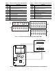
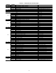
Specifications
29
CONTROL FUNCTIONS
Overview —
The ComfortLink™ controls and software
have a large number of features that will meet the requirements
of broad range of applications. The controls are pre-configured
from the factory for the various factory-installed options, but
there will be field configurations required to setup the unit for
particular applications and field-installed accessories.
Common VAV and CV Standard Features:
• Cooling capacity control of up to four compressors and one
minimum load valve (MLV), to maintain required space
conditions during occupied and unoccupied periods.
• Automatic lead-lag of the compressors which changes at
full and zero load.
• Minimum compressor on and off times for oil return and
compressor reliability.
• Monitoring of suction pressure using pressure transducers
for diagnostics and coil freeze protection.
• Control of two outdoor condenser fan contactors based on
saturated condensing temperature and outdoor air tempera-
ture for head pressure control.
• Support of Motormaster® V control for low ambient head
pressure control if needed (the most energy efficient unit
will use an economizer and free cooling at low ambient con-
ditions).
• Control of modulating economizer damper to provide free
cooling when outdoor conditions are suitable, using Supply-
Air Temperature as the basis of the control point A digitally
controlled economizer is used which provides diagnostic
feedback.
• Economizer changeover control by dry bulb, differential dry
bulb, enthalpy, differential enthalpy or max dew point cus-
tom curve. Instead of the conventional enthalpy sensor or
switch, this control uses a dry bulb sensor and a humidity
sensor and then calculates the enthalpy. The standard A, B,
C, and D enthalpy changeover curves are also stored in the
software. Direct readout of the humidity is available as well
as other features due to the use of the humidity sensor.
• Three-position economizer damper relay control for fixed
ventilation applications. Unit also has a mechanical 2-position
damper for applications that cannot use an economizer, but
require ventilation air for IAQ control.
• Support of demand control ventilation through a reset of the
economizer’s minimum position. This reset based on differ-
ential CO
2
PPM (outdoor and indoor) can be chosen as
linear or as fast or slow-acting exponential curves.
• Support of Remote Occupied/Unoccupied input to start/stop
the unit.
• Control of the Economizer Damper and Indoor Fan to
obtain Night Time Free Cooling.
• Pre-Occupancy IAQ Purge function.
• Building Pressure control via four or six Power-Exhaust
Fan relay outputs. The building pressure sensor is read
directly by the ComfortLink controls and can be configured
through the unit display.
• Demand Limit function based on demand limit switches or
demand limit 4 to 20 mA external signal or CCN Loadshed
POC commands.
• Alarm monitoring of all key parameters.
• Communications support on the CCN and LEN network.
• Full electronic 365-day timeclock with backup capability.
Timeclock supports hour, minute, day of week, month, date
and year.
• Daylight Savings Time function.
• Occupancy control with 8 periods for unit operation.
• Holiday Table containing up to 30 holidays within the
control.
• Ability to initiate timed override from T55, T56 and T58
devices.
• Ability to use multiple space temperature sensors (T55
only) to average Space Temperature external to the control.
• Ability to support the CCN communicating T58 sensor.
• Factory Test for end of production line tests.
• Temperature Compensated Start algorithm to calculate early
start time before the occupancy period.
• Linkage function for interface with a ComfortID™ system.
• Support of Display, Maintenance, Configuration, Service,
and Set Point data tables for interface with Building
Supervisor, Service Tool, ComfortVIEW™, and Comfort-
WORKS® software.
• Control of up to 6 relay outputs for gas or electric heat to
maintain a heating set point. Note that when this is used on
VAV systems the HIR (heat interlock relay) must be
connected to the terminal controls to drive the dampers
open.
• Control using conventional (Y1, Y2, W1, W2, G) thermo-
stat inputs (TSTAT control) (CV only).
• Ability to have up to 6 stages of capacity with a conven-
tional Y1, Y2, W1, W2 thermostat using a high and low
cooling and heat logic (CV only).
• Support of a minimum load hot gas bypass valve for low
load applications. Valve is controlled directly by the control
and is an additional step of capacity as well as a low evapo-
rator protection device.
• Adjustment of space set points (configurable amount ± 1 to
10° F) when using T-56 sensor (SPTO) (CV only).
• Control of an Indoor Fan/Supply Fan relay.
• Enable Heating or Cooling during Unoccupied periods as
required to maintain Space Temperature within the unoccu-
pied set points.
• Provide Discrete inputs for Fan Status, Filter Status, and
Field Applied Status.
• Provide an output for the external Alarm Light Indicator.
• Integral return air smoke detector.
• Smoke Control modes including Evacuation, Smoke Purge,
Pressurization, and Fire Shutdown (CEM required).
• Provide power exhaust outputs for direct control of modu-
lated power exhaust stages during Fire/Smoke modes.
• Enable Heating or Cooling during Unoccupied periods as
required by Nighttime thermostat inputs, or to maintain
Space Temperature or Return-Air Temperature within the
unoccupied set points.
VAV Only Standard Features:
• Supply Duct Static Pressure Control by means of a 4 to 20
mA controlled VFD.
• Support of external Supply Air Temperature Reset analog
input to reset supply air set point upward (CEM required).
• Control of a heat-interlock relay, which must be used for
ensuring that the terminals are providing the minimum
CFM for heating.
• Space Temperature Reset algorithm to reset Supply Air
set point upward when Space Temperature falls below its
occupied cooling set point.
• Provide duct static pressure reset support for linkage with
air terminals.