
Specifications

26
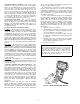
MOTORMASTER® V CONTROL — For operation below
32 F when an economizer is not used, the units can be equipped
with an accessory Motormaster V control, which controls the
speed of the stage 1 condenser fans. The Motormaster V con-
trol is a 3-phase inverter that controls the speed of the fans
based on a pressure transducer connected to the liquid line. On
20 to 35 ton units, one fan will be controlled. On 40 to 60 ton
units, two fans will be controlled. For units equipped with an
economizer, there should not be a need for this control because
the economizer can provide free cooling using outside air,
which will be significantly lower in operating cost.
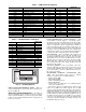
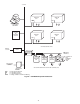
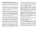
ACCESSORY NAVIGATOR — The accessory handheld
Navigator display can be used with the 48/50A series units. See
Fig. 19. The Navigator operates the same way as the Scrolling
Marquee device. The ECB1 and ECB2 boards contain a sec-
ond LEN port (J3 connection) than can be used with the hand-
held Navigator display.
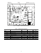
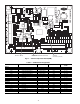
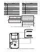
CONTROL MODULE COMMUNICATIONS
Red LED
— Proper operation of the control boards can be
visually checked by looking at the red status LEDs as shown
on Fig. 10-13. When operating correctly, the red status LEDs
should blink in unison at a rate of once every 2 seconds. If the
red LEDs are not blinking in unison, verify that correct power
is being supplied to all modules. Also, be sure that the Main
Base Board is supplied with the current software. If necessary,
reload current software. If the problem still persists, replace the
MBB. A board LED that is lit continuously or blinking at a rate
of once per second or faster indicates that the board should be
replaced.
Green LED
— The boards also have a green LED, which is
the indicator of the operation of the LEN communications,
which is used for communications between the boards. On the
MBB board the Local Equipment Network (LEN) LED should
always be blinking whenever power is on. All other boards
have a LEN LED that will blink whenever power is on and
there is communication occurring. If LEN LED is not blinking,
check LEN connections for potential communication errors (J3
and J4 connectors). A 3-wire sensor bus accomplishes commu-
nication between modules. These 3 wires run in parallel from
module to module.
Yellow LED
— The MBB has one yellow LED. The Carrier
Comfort Network (CCN) LED will blink during times of
network communication. The other boards do not have a CCN
communications port.
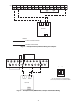
CARRIER COMFORT NETWORK INTERFACE — The
48/50A series units can be connected to the CCN if desired.
The communication bus wiring is a shielded, 3-conductor cable
with drain wire and is field supplied and installed. See the
Installation instructions for wiring information. The system
elements are connected to the communication bus in a daisy
chain arrangement. The positive pin of each system element
communication connector must be wired to the positive pins of
the system elements on either side of it. This is also required
for the negative and signal ground pins of each system element.
Wiring connections for CCN should be made at TB3. See
Fig. 20. Consult the CCN Contractor’s Manual for further
information.
NOTE: Conductors and drain wire must be 20-AWG
(American Wire Gage) minimum stranded, tinned copper.
Individual conductors must be insulated with PVC, PVC/
nylon, vinyl, Teflon, or polyethylene. An aluminum/polyester
100% foil shield and an outer jacket of PVC, PVC/nylon,
chrome vinyl, or Teflon with a minimum operating tempera-
ture range of –20 C to 60 C is required.
It is important when connecting to a CCN communication
bus that a color-coding scheme be used for the entire network
to simplify the installation. It is recommended that red be used
for the signal positive, black for the signal negative and white
for the signal ground. Use a similar scheme for cables contain-
ing different colored wires.
At each system element, the shields of its communication
bus cables must be tied together. If the communication bus is
entirely within one building, the resulting continuous shield
must be connected to a ground at one point only. If the commu-
nication bus cable exits from one building and enters another,
the shields must be connected to grounds at the lightning
suppressor in each building where the cable enters or exits the
building (one point per building only). To connect the unit to
the network:
1. Turn off power to the control box.
2. Cut the CCN wire and strip the ends of the red (+), white
(ground), and black (–) conductors. (Substitute appropri-
ate colors for different colored cables.)
3. Connect the red wire to (+) terminal on TB3 of the plug,
the white wire to COM terminal, and the black wire to the
(–) terminal.
4. The RJ14 CCN connector on TB3 can also be used, but is
only intended for temporary connection (for example, a
laptop computer running Service Tool).
5. Restore power to unit.
IMPORTANT: A shorted CCN bus cable will prevent
some routines from running and may prevent the unit
from starting. If abnormal conditions occur, unplug the
connector. If conditions return to normal, check the
CCN connector and cable. Run new cable if necessary.
A short in one section of the bus can cause problems
with all system elements on the bus.
R
un
S
tatus
S
ervice
Test
T
em
pe
ratures
P
re
ssure
s
S
etpoints
Inputs
O
utputs
C
onfiguration
Tim
e
C
lo
ck
O
perating
M
odes
A
larm
s
ENTER
ESC
MODE
Alarm Status
TIME
EWT
LW
T
SETP
12.58
54.6
° F
44.1
° F
44.0° F
NAVIGATOR
ComfortLink
Fig. 19 — Accessory Navigator Display