
Specifications


25
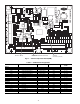
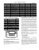
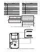
Table 8 — VFD (S9 Inverter) Terminal Designations Table 9 — VFD (E3 Inverter) Terminal Designations
TERMINAL FUNCTION
L1 (R)
L2(S)
L3(T)
Three-Phase Main Circuit Input Power Supply.
T1(U)
T2(V)
T3(W)
Three-Phase AC Output to Motor
0 V to Maximum Input Voltage Level
R
C
Configured to auto start motor in the reverse
direction as required by fan/motor configuration.
II (+)
CC(–)
NotusedfortheAseries.
P24 (+)
II (–)
Factory set for 4-20 mA input from the ECB2 board
through the isolator board.
S3
CC(–)
NotUsedfortheASeries.
S2
CC(–)
NotUsedfortheASeries.
SI
CC(–)
NotUsedfortheASeries.
TERMINAL FUNCTION
L1 (R)
L2(S)
L3(T)
Three-Phase Main Circuit Input Power Supply.
T1(U)
T2(V)
T3(W)
Three-Phase AC Output to Motor
0 V to Maximum Input Voltage Level
CC
ST
Inverter Enable
Factory-Supplied jumper cross CC& ST.
R
CC
Configured to auto start motor in the reverse direction
as required by fan/motor configuration.
S4
CC
Factory supplied jumper. When opened the drive
goes to emergency stop.
S1
CC
Not used for the A series.
P24
IV
Factory wired for 4-20 mA remote input from ECB2 board
through the isolation board.
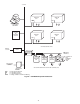
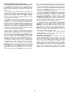
13579111315
246810121416
12345678
R Y1Y2W1W2G C X
13579111315
246810121416
TB5
TB6
TB3
TB4
C
LEN
CCN
CCN
+
-
GRD
J6
TB4
1
2
3
4
5
6
7
1
2
3
4
5
6
7
TB5
UNIT CONTROL BOX
1
2
J3
J5
J4
B4
OVERRIDE
3
2
1
1
2
3
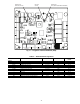
Fig. 17 — Field Connection Terminal Strips (Main Control Box)
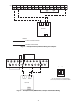
Fig. 18 — CO
2
and Space Temperature Sensor Wiring (33ZCT55CO2 and 33ZCT56CO2)