
Specifications


23
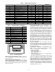
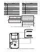
Table 6 — CEM Channel Assignments
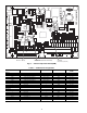
Table 7 — IGC Board Inputs and Outputs
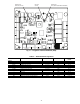
FIELD CONNECTION TERMINAL STRIPS — Field con-
nection terminal strips are located in the main control box. See
Fig. 17 and Table 10.
Accessory Control Components — In addition to
the factory-installed options, the units can also be equipped
with several field-installed accessories that expand the control
features of the unit. The following hardware components can
be used as accessories.
ROOM THERMOSTATS (48/50AJ,AW ONLY) — The
ComfortLink™ Controls support a conventional electro-
mechanical or electronic thermostat that uses the Y1, Y2, W1,
W2, and G signals. The control also supports an additional in-
put for an occupied/unoccupied command that is available on
some new thermostats. The ComfortLink control can be con-
figured to run with multiple stages of capacity which allows up
to 6 stages of capacity. Although the unit can be configured for
normal 2-stage control, it is recommended that the multi-stage
control be used. The room thermostat is connected to TB4.
SPACE SENSOR — The ComfortLink control supports the
use of space temperature sensors. The T55 and T56 sensors
and CCN communicating T58 room sensor can be used. The
T55 and T56 sensors are connected to TB5 terminal 3, 4, and 5.
The T58 sensor is connected to the CCN connections on TB3.
When a T55, T56, or T58 sensor is used, the user must install
the red jumpers from R to W1, and W2 on TB4 for the heat
function to work correctly.
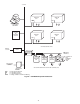
SPACE CO
2
SENSORS — The ComfortLink control also
supports a CO
2
IAQ sensor that can be located in the space for
useindemandventilation.Thesensormustbea4to20mA
sensor and should be connected to TB5 terminal 6 and 7. See
Fig. 18 for sensor wiring.
ECONOMIZER HUMIDITY CHANGEOVER SEN-
SORS — The ComfortLink controls support 5 different
changeover schemes for the economizer. These are:
• Outdoor Air Dry Bulb
• Differential Dry Bulb
• Outdoor Air Enthalpy Curves
• Differential Enthalpy
• Custom Curves (a combination of an enthalpy/dewpoint
curve and a dry bulb curve).
The units are equipped as standard with an outside air and
return air dry bulb sensor which supports the dry bulb
changeover methods. If the other methods are to be used, then a
field-installed humidity sensor must be installed for outdoor air
enthalpy and customer curve control and two humidity sensors
must be installed for differential enthalpy. Installation holes are
pre-drilled and wire harnesses are installed in every unit for
connection of the humidity sensors. The ComfortLink Control
converts the measured humidity into enthalpy, dewpoint, and
the humidity changeover curves.
POINT NAME POINT DESCRIPTION TYPE OF I/O I/O POINT NAME
CONNECTOR
PIN NO.
INPUTS
FAN.S Supply Fan Status switch Switch DI 1 J7, 1-2
DLM.1 Demand Limit — Redline Switch DI 2 J7, 3-4
DLM.2 Demand Limit — Load Shed Switch DI 3 J7, 5-6
F.PRS Fire Pressurization Switch DI 4 J7, 7-8
F.EVC Fire Evacuation Switch DI 5 J7, 9-10
F.PRG Smoke Purge Switch DI 6 J7, 11-12
IAQ Indoor Air Quality Override Switch Switch DI 7 J7, 13-14
Not Used at this Time 4-20 mA AN7 J6, 1-3
DM.AI 4-20mA Demand Limit 4-20 mA AN8 J6, 4-6
rm.sp 4-20mA Supply Air Setpoint 4-20 mA AN9 J6, 7-9
OAQ Outside Air CO
2
Sensor 4-20 mA AN10 J6, 10-12
— Not Used — AN1 J5, 1-2
— Not Used — AN2 J5, 3-4
— Not Used — AN3 J5, 5-6
— Not Used — AN4 J5, 7-8
— Not Used — AN5 J5, 9-10
— Not Used — AN6 J5, 11-12
POINT NAME POINT DESCRIPTION
CONNECTOR
PIN NO.
INPUTS
RT 24 Volt Power Supply R1,C
W Heat Demand 2
GFan 3
LS Limit Switch 7,8
RS Rollout Switch 5,6
SS Hall Effect Sensor 1,2,3
CS Centrifugal Switch (Not Used) 9,10
FS Flame Sense FS
OUTPUTS
CM Induced Draft Motor CM
IFO Indoor Fan IFO
R 24 Volt Power Output (Not Used) R
SPARK Sparker —
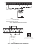
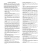
LED Display LED
Run Status
Service Test
Temperature
Pressures
Setpoints
Inputs
Outputs
Configuration
Time Clock
Operating Modes
Alarms
Alarm Status
ENTER
MODE
ESCAPE
Fig. 14 — Scrolling Marquee