
Specifications


CL-4
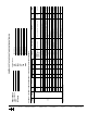
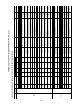
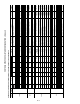
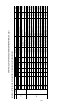
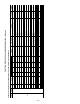
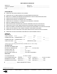
CONTROLS SETUP CHECKLIST AND CONFIGURATION LOG (cont)
RECORD ALL SETPOINTS AND CONFIGURATIONS LISTED BELOW FOR FUTURE REFERENCE
SUBMODE
SUB
SUBMODE
ITEM SETTING
UNITS FACTORY DEFAULT
RANGE
ENGLISH
ITEM EXPANSION COMMENTS CCN TABLE
CCN POINT
NAME
English Metric VAV CV
SVFD
SVFD SF VFD Parameters
SP.S DSBL ENBL ENBL/DSBL Duct Static Pressure Sensor
Enables and disables the use of a supply duct
pressure sensor
UNIT SPSENS
SP.C — — none VFD Control
1=NONE,
2=VFD CONTROL
Static Pressure Control
Enables to use of VFD control for building pressure
control. Only applies to VAV
CONFIG STATICFG
SF.MN % % 20 20 20 TO 40 IDF VFD Minimum Speed
minimum VFD speed, do not set on inverters which
must be set to 0
SFANVFD SVFD_MIN
SF.MX % % 100 100 50 to 100 IDF VFD Maximum Speed maximum VFD speed SFANVFD SVFD_MAX
SF.FS % % 100 100 0 T0 100 IDF Speed In Fire Mode VFD speed in fire modes SFANVFD SVFD_FSD
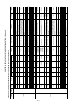
SP.KP — — 20 20 0.0 TO 100.0 Prop. Gain SF VFD
Control Loop Porportional Gain Factor (do not
change)
SFANVFD SPKP
SP.KD — — 0 0 0 TO 50.0 Diff. Gain SF VFD
Control Loop Differential Gain Factor (do not
change)
SFANVFD SPKD
SP.KI — — 2 2 0.0 TO 50.0 Integral Gain SF VFD Control Loop Integral Gain Factor (do not change) SFANVFD SPKI
SP.K — — 1 1 0.0 TO 50.0 System /gain SF VFD Control Loop gain Factor (do not change) SFANVFD SPK
SP.DT sec sec 2 2 1 TO 200 VFD PID Time (Seconds) Control Loop PID time Factor (do not change) SFANVFD VFD_TIME
SP.H.L in-H2O cm-H2O 5 5 -10.0 TO 10.0 Duct Press Sensor HI end
used to set upper range on the supply duct
pressure
SENSWORK,
SENSCNFG
SP_HIGH
SP.L.L in-H2O cm-H2O 0 0 -10.0 TO 10.0 Duct Press Sensor Lo end
used to set the lower range on the supply duct
pressure
SENSWORK,
SENSCNFG
SP_LOW
BP
Building Pressure Params Building pressure control configurations
BP.SL — — 2 2 1,2,3 Modulating PE Alg Select 1,2,3 use routine 2 (do not change) BP_CNTL BPSELECT
BP.S — — DSBL DSBL ENBL/DSBL Building Pressure Sensor enables the use of the building pressure sensor UNIT BPSENS
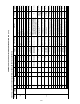
BP.R in-H2O cm-H2O 0.25 0.25 0 TO 1 Bldg Press (+/-) Range use to set range of sensor (+/- limit)
SENSWORK,
SENSCNFG
BP_RANGE
BP.ZG — — 1 1 0.1 TO 10 BP Threshold Adjustment Threshold adjustment (do not change) BP_CNTL BPZ_GAIN
BP.DT MIN 1 1 1 TO 10 BP PID Evaluation PID factor (do not change) BP_CNTL BPPERIOD
BP.HP in-H2O cm-H2O 0.05 0.05 0 TO 1.0 High BP Level
Building Pressure Upper Differential limit
(use with routine 2)
BP_CNTL BPHPLVL
BP.LP in-H2O cm-H2O 0.04 0.04 0 TO 1.0 Low BP Level
Building Pressure Lower Differential limit
(use with routine 2)
BP_CNTL BPLPLVL
IAQ
IAQ Configuration Demand Ventilation Configuration
IA.CF — — 0 0
0=NO IAQ, 1=DCV,
2=OVERRIDE IAQ,
3=CNTL MIN POS,
4=MIN POS POT,
IAQ MinPos Sensor Config Used to configure the use of IAQ control
AIR_QLTY,
AIRQUALT
IAQANCFG
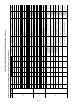
IA.FN — — 0 0
0=NEVER,
1=OCCUPIED,
2=OVERRIDE IAQ
IAQ 4-20 ma Fan Config
Used to configure IAQ fan control when using the
4-20 ma input
AIR_QLTY,
AIRQUALT,
ECONMIN
IAQANFAN
IA.I.C — — 0 0
0=NO IAQ,
1=DCV,
2=OVERRIDE IAQ
IAQ Discrete Input Config Used to configure IAQ discrete input
AIR_QLTY,
AIRQUALT,
ECONMIN
IAQINCFG
IA.I.F — — 0 0
0=NEVER,
1=OCCUPIED,
2=ALWAYS
IAQ Disc.In Fan Config
Used to configure fan control when using the IAQ
discrete fan input
AIR_QLTY,
AIRQUALT,
ECONMIN
IAQINFAN
AQ.MP % % 0 0 0 TO 100 IAQ Demand Vent Min Pos. minimum position when IAQ below limit
BLDGPRES,
ECONWORK,
SET_PNT,
AIRQUALT,
ECONMIN
IAQMINP
MIN.I % % 20 20 0 TO 100 Economizer Min Position
Economizer minimum occupied position, reference
valve should be set in setpoint screen
BLDGPRES,
ECONWORK,
SET_PNT,
AIRQUALT,
ECONMIN
ECONOMIN