
Specifications


CL-2
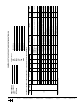
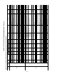
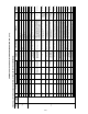
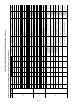
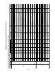
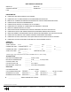
CONTROLS SETUP CHECKLIST AND CONFIGURATION LOG (cont)
RECORD ALL SETPOINTS AND CONFIGURATIONS LISTED BELOW FOR FUTURE REFERENCE
SUBMODE
SUB
SUBMODE
ITEM SETTING
UNITS FACTORY DEFAULT
RANGE
ENGLISH
ITEM EXPANSION COMMENTS CCN TABLE
CCN POINT
NAME
English Metric VAV CV
COOL
COOL — — Cooling Configuration Cooling Control Configurations
HP.SP F C 110 110 80.0 to 150.0 Head Pressure Setpoint Setpoint for head pressure control UNIT HPSP
C.L.OA F C 40 40 -20 TO 40 Compressor Lockout Temp
Temperature below which compressors will be
locked out
COOL_CFG OATLCOMP
C.FOD SEC SEC 60 60 0 TO 600 Fan-Off Delay, Mech Cool
Delay in sec to turn off fan when using cyclic
incoor fan control in cooling
COOL_CFG COOL_FOD
C.TC.F MIN MIN 0 0 0 TO 60 TCST Cool Time/Temp Fact
Temperature compensated start configuration
which is used to determine advanced start time
before occupancy based on the following equa-
tion prestart time = (SPT-OC.SP)*KCOOL. 0,
disables temperaturre compensated start
CONFIG KCOOL
Z.GN — — 1 1 -10.0 TO 10.0 Capacity Threshold Adjust
capacity control PID loop gain factor, normally
set to 1
COOL_CFG Z_GAIN
A1.EN — — YES YES ENBL/DSBL Enable Compressor A1 Used to disable compressors in case of failure COOL_CFG CMPA1ENA
A2.EN — — NO NO ENBL/DSBL Enable Compressor A2 Used to disable compressors in case of failure COOL_CFG CMPA2ENA
B1.EN — — YES YES ENBL/DSBL Enable Compressor B1 Used to disable compressors in case of failure COOL_CFG CMPB1ENA
B2.EN — — NO NO ENBL/DSBL Enable Compressor B2 Used to disable compressors in case of failure COOL_CFG CMOB2ENA
A1.C.E — — YES YES ENBL/DSBL CSB A1 Feedback Alarm Must be enabled if the compessor is enabled COOL_CFG CSB_A1EN
A2.C.E — — NO NO ENBL/DSBL CSB A2 Feedback Alarm Must be enabled if the compessor is enabled COOL_CFG CSB_A2EN
B1.C.E — — YES YES ENBL/DSBL CSB B1 Feedback Alarm Must be enabled if the compessor is enabled COOL_CFG CSB_B1EN
B2.C.E — — NO NO ENBL/DSBL CSB B2 Feedback Alarm Must be enabled if the compessor is enabled COOL_CFG CSB_B2EN
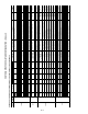
HEAT
— — Heating Configurations Gas and Electric Heating Configurations
HT.TY — — NO HEAT NO HEAT
0=NO HEAT,
1=ELECTRIC,
2=2-STAGE GAS,
3=STAGED GAS
Heat Type (0,1,2,3) Used to select the type of heating HEAT_CFG HEATTYPE
N.HST — — 2 STAGE 2 STAGE
0=2 STAGE,
1=5 STAGE,
2=7 STAGE,
3=9 STAGE,
4=11 STAGE
Heat Stage Type
Used only for staged gas heat and selects the
sequence that will be used
HEAT_CFG HTSTGTYP
OCC.H — — NO NO NO/YES Occuped Heating Enabled Enables occupied heating for VAV
HEATSTAT,
HEAT_CFG,
CONFIG
HTOCCENA
LAT.M — — NO NO NO/YES SAT Sensor Sense Heat
Yes = EDT sensor relocated to leaving
ductwork which in needed for Linkage heat
monitoring
HEATSTAT HTLATMON
E.FOD SEC SEC 30 30 10 TO 600 Fan-Off Delay, Elec Heat delay in turning off fans for electric heat HEAT_CFG ELEC_FOD
G.FOD SEC SEC 45 45 45 TO 600 Fan-Off Delay, Gas heat delay in turing off fans for gas heat HEAT_CFG GAS_FOD
H.T.CF MIN MIN 0 0 0 TO 60 TCST Heat Time/Temp Fact
Used for temperature compensated start in the
heat mode and the prestart time prior to occu-
pancy is calculated by Time =TCST time -
Kheat *(ohsp - space temp). 0 Disables the
function
CONFIG KHEAT
S.CP.M % % 45 45 5 TO 45 Max Cap Change Per Cycle
Max % capacity that can be added/removed at
any time for staged heat control
HEATSTAT HTCAPMAX
S.PI.R — — 90 90 60 TO 300 PID Algorithm Rate
Staged gas PID factor, normally should not be
changed
HEATSTAT HTSGPIDR
S.RIS — — 90 90 60 TO 300 PID algorithm rate Staged Gas rise clamp HEATSTAT HTSGPIDR
S.MR.D — — 0.5 0.5 0 TO 5.0 S. Gas DB Min.DF/PID Rate PID rate of change factor HEATSTAT HT_MR_DB
S.DB F F 2 2 0 TO 5.0 ST.Gas Temp. Dead Band Deadband where changes will not be made HEATSTAT HT_SG_DB
S.P.GN — — 1 1 0 TO 1.5 Proportional Gain PID porportional gain factor HEATSTAT HT_PGAIN
S.I.GN — — 1 1 0 TO 1.5 Integral Gain PID integral gain factor HEATSTAT HT_IGAIN
S.DGN — — 1 1 0 TO 1.5 Derivative Gain PID dreivative gain factor HEATSTAT HT_DGAIN