
Specifications


116
APPENDIX A — CCN TABLES
All A series units with ComtfortLink™ Controls have a port
for interface with the Carrier Comfort Network (CCN). On
TB3 there is a J11 jack which can be used for temporary con-
nection to the CCN network or to computers equipped with
CCN software like the Service Tool. Also on TB3 there are
screw connections that can be used for more permanent CCN
connections.
In the following tables the structure of the tables which are
used with the Service tool as well as the names and data that
are included in each table are shown. As a reference the equiv-
alent Scrolling Marquee tables and names are included. There
are several CCN variables that are not displayed through the
Scrolling Marquee and are used for more extensive diagnostics
and system evaluations.
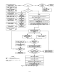
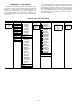
SERVICE TOOL AND CCN TABLES
GRAPHICS POINTS MODIFY REMOVE DIAGNOSTICS CONTROLLER-TIME QUIT
BLDGPRES TIME-SCHED SERVICE
CAPACITY PERIOD 1 ALRTLMTS
CIRCUITA PERIOD 2 DISLOGIC
CIRCUITB PERIOD 3 SENSCNFG
ECONWORK PERIOD 4 MAINTENANCE
ENTHALPY PERIOD 5 AIRQUALT
FLTSWORK PERIOD 6 ALARMS
HEATSTAT PERIOD 7 ANALOGIN
SENSWORK PERIOD 8 COMPWORK
SFS_WORK SETPNT-SCHED DMDLIMIT
STATUS1 GRAPHICS ECONDIAG
STATUS2 CONTROLLER ECONMIN
TSTAT AIR_QLTY EDT_WORK
ALARMDEF INPUTS
BP_CTRL LINKDEFM
BRODEFS MODES
CDMD_CFG OCCDEFME
CONFIG OUTPUTS
COOL_CFG STRTHOUR
CTLR-ID TESTOUTS
DISPLAY VERSIONS
DMD_LIM VERIFY-CONFIG
HEAT_CFG ALARM-HISTORY
HOLIDAY
OCCDEFCS
SCHEDOVR
SET_PNT
SFANVFD
UNIT
NAMES
UPLOAD
DOWNLOAD
Not used
on this
unit
Used to
remove
controller
from list
Used to read
controller
time
information
Used to exit
the
Service Tool