
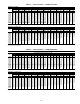
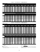
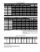
Specifications

107
LOW CHARGE COOLING — Connect the gage set and a
temperature measuring device to the liquid line. Ensure that all
condenser fans are operating. It may be necessary to block part
of the coil on cold days to ensure that condensing pressures are
high enough to turn on the fans. Adjust the refrigerant change
in each circuit to obtain 20 F ± 2 F of liquid subcooling.
NOTE: Indoor-air cfm must be within normal operating range
of unit.
Thermostatic Expansion Valve (TXV) — Each circuit
has a TXV. The TXV is nonadjustable and is factory set to main-
tain 10 to 13° F superheat leaving the evaporator coil. The TXV
controls flow of liquid refrigerant to the evaporator coils.
Gas Valve Adjustment
NATURAL GAS — The 2-stage gas valve opens and closes
in response to the thermostat or limit control.
When power is supplied to valve terminals 3 and 4, the pilot
valve opens to the preset position. When power is supplied to
terminals 1 and 2, the main valve opens to its preset position.
The regular factory setting is stamped on the valve body
(3.5 in. wg).
To adjust regulator:
1. Set thermostat at setting for no call for heat.
2. Turn main gas valve to OFF position.
3. Remove
1
/
8
-in. pipe plug from manifold. Install a water
manometer pressure-measuring device.
4. Set main gas valve to ON position.
5. Set thermostat at setting to call for heat (high fire).
6. Remove screw cap covering regulator adjustment screw
(See Fig. 36).
7. Turn adjustment screw clockwise to increase pressure or
counterclockwise to decrease pressure.
8. Once desired pressure is established, set unit to no call for
heat (3.3-in. wg high fire).
9. Turn main gas valve to OFF position.
10. Remove pressure-measuring device and replace
1
/
8
-in.
pipe plug and screw cap.
11. Turn main gas valve to ON position and check heating
operation.
Main Burners — For all applications, main burners are
factory set and should require no adjustment.
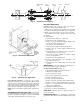
MAIN BURNER REMOVAL (Fig. 37)
1. Shut off (field-supplied) manual main gas valve.
2. Shut off power supply to unit.
3. Remove heating access panel.
4. Disconnect gas piping from gas valve inlet.
5. Remove wires from gas valve.
6. Remove wires from rollout switch.
7. Remove sensor wire and ignitor cable from IGC board.
8. Remove 2 screws securing manifold bracket to basepan.
9. Remove 4 screws that hold the burner support plate
flange to the vestibule plate.
10. Lift burner assembly out of unit.
11. Reverse procedure to re-install burners.
Filter Drier — Replace whenever refrigerant system is ex-
posed to atmosphere.
Replacement Parts — A complete list of replacement
parts may be obtained from any Carrier distributor upon request.
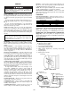
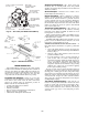
CENTER DRIVE
SHAFT
FLEX
MEMBER
SHAFT
FLANGE
BEARINGSSHAFT
Fig. 33 — Evaporator Fan Coupling
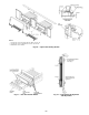
Fig. 34 — Belt Tension Adjustment
Fig. 35 — Condenser-Fan Adjustment