
Specifications

104
SERVICE
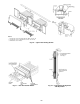
Service Access —
All unit components can be reached
through clearly labelled hinged access doors. These doors are
not equipped with tiebacks, so if heavy duty servicing is need-
ed, either remove them or prop them open to prevent accidental
closure.
Each door is held closed with 3 latches. The latches are se-
curedtotheunitwithasingle
1
/
4
-in. - 20 x
1
/
2
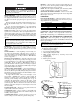
-in. long bolt. See
Fig. 28.
To open, loosen the latch bolt using a
7
/
16
-in. wrench. Pivot
the latch so it is not in contact with the door. Open the door. To
shut, reverse the above procedure.
NOTE: Disassembly of the top cover may be required under
special service circumstances. It is very important that the ori-
entation and position of the top cover be marked on the unit
prior to disassembly. This will allow proper replacement of the
top cover onto the unit and prevent rainwater from leaking into
the unit.
Cleaning — Inspect unit interior at beginning of each heat-
ing and cooling season and as operating conditions require.
Remove unit side panels and/or open doors for access to unit
interior.
MAIN BURNERS — At the beginning of each heating sea-
son, inspect for deterioration or blockage due to corrosion or
other causes. Observe the main burner flames and adjust if nec-
essary. Check spark gap. See Fig. 29. Refer to Main Burners
section on page 107.
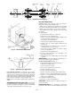
FLUE GAS PASSAGEWAYS — The flue collector box and
heat exchanger cells may be inspected by removing gas section
access panel, flue box cover, collector box, and main burner as-
sembly (Fig. 30 and 31). Refer to Main Burners section on
page 107 for burner removal sequence. If cleaning is required,
clean all parts with a wire brush. Reassemble using new high-
temperature insulation for sealing.
COMBUSTION-AIR BLOWER — Clean periodically to as-
sure proper airflow and heating efficiency. Inspect blower
wheel every fall and periodically during heating season. For the
first heating season, inspect blower wheel bi-monthly to deter-
mine proper cleaning frequency.
To inspect blower wheel, remove heat exchanger access
panel. Shine a flashlight into opening to inspect wheel. If
cleaning is required, remove motor and wheel assembly by
removing screws holding motor mounting plate to top of
combustion fan housing (Fig. 30 and 31). The motor, scroll,
and wheel assembly can be removed from the unit. Remove
scroll from plate. Remove the blower wheel from the motor
shaft and clean with a detergent or solvent. Replace motor and
wheel assembly.
EVAPORATOR COIL — Remove access panels and clean as
required with commercial coil cleaner.
CONDENSER COIL — Clean condenser coil annually and
as required by location and outdoor-air conditions. Inspect coil
monthly; clean as required.
CONDENSATE DRAIN — Check and clean each year at
start of cooling season. In winter, keep drains and traps dry.
FILTERS — Clean or replace at start of each heating and cool-
ing season, or more often if operating conditions require. Refer
to Installation Instructions for type and size.
NOTE: The unit requires industrial grade throwaway filters
capable of withstanding face velocities up to 625 fpm.
OUTDOOR-AIR INLET SCREENS — Clean screens with
steam or hot water and a mild detergent. Do not use disposable
filters in place of screens.
Lubrication
FAN SHAFT BEARINGS — Lubricate bearings at least ev-
ery 6 months with suitable bearing grease. Do not over grease.
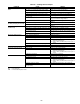
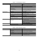
Typical lubricants are given below:
*Preferred lubricant because it contains rust and oxidation inhibitors.
CONDENSER- AND EVAPORATOR-FAN MOTOR BEAR-
INGS — The condenser- and evaporator-fan motors have
permanently sealed bearings, so no field lubrication is necessary.
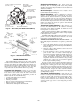
Evaporator Fan Performance Adjustment
(Fig. 32) —
Fan motor pulleys are designed for speed
shown in Physical Data table in unit Installation Instructions
(factory speed setting).
To change fan speeds, change pulleys.
To align fan and motor pulleys:
1. Shut off unit power supply.
2. Loosen fan shaft pulley bushing.
3. Slide fan pulley along fan shaft.
4. Make angular alignment by loosening motor from
mounting plate.
5. Retighten pulley.
6. Return power to the unit.
Before performing service or maintenance operations on
unit, turn off main power switch to unit. Electrical shock
could cause personal injury.
IMPORTANT: After servicing is completed, make sure
door is closed and relatched properly, and that the latches
are tight. Failure to do so can result in water leakage into
the evaporator section of the unit.
MANUFACTURER LUBRICANT
Texaco Regal AFB-2*
Mobil Mobilplex EP No. 1
Sunoco Prestige 42
Texaco Multifak 2
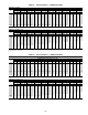
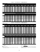
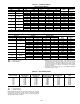
IMPORTANT: Check to ensure that the unit drive matches
the duct static pressure using Tables 42-65.
Fig. 28 — Door Latch
Fig. 29 — Spark Gap Adjustment