48/50A020-060 Single Package Large Rooftop Units with Scroll Compressors and ComfortLink™ Version 2.X Controls Controls, Start-Up, Operation, Service and Troubleshooting CONTENTS Page Page SAFETY CONSIDERATIONS . . . . . . . . . . . . . . . . . . . . . . . 2 GENERAL . . . . . . . . . . . . . . . . . . . . . . . . . . . . . . . . . . . . . . 2-4 Configurable Features . . . . . . . . . . . . . . . . . . . . . . . . . . . . . 3 Constant Volume Features. . . . . . . . . . . . . . . . . . . . . . . . .
CONTENTS (cont) GENERAL Page This book contains Start-Up, Controls, Operation, Troubleshooting and Service information for the 48/50A series rooftop units. See Table 1. These units are equipped with ComfortLink™ controls. TROUBLESHOOTING . . . . . . . . . . . . . . . . . . . . . . . . 108-115 Complete Unit Stoppage . . . . . . . . . . . . . . . . . . . . . . . . . 108 Single Circuit Stoppage . . . . . . . . . . . . . . . . . . . . . . . . . 108 Service Analysis . . . . . . . . . . . . . . . . . . . . . .
Configurable Features — The unit and the controls • Enable heating (if installed) or cooling during unoccupied periods as required to maintain space temperature within the unoccupied set points. • Support of demand limiting using external switch inputs or an external 4 to 20 mA signal. • For units connected to the CCN (Carrier Comfort Network), the user can also display all the unit information including I/O values for Maintenance, Configuration, Service, and Set Point data tables.
Variable Air Volume (VAV) Features — The 48/ Factory-Installed Components 50AK,AY units are designed to operate in VAV applications. As standard, the units include a supply fan VFD to control the supply cfm and duct pressure. The units are designed to control the leaving-air temperature in cooling to configurable set points. The control, depending on the selected options and accessories, will operate in one of three primary modes which are heating, ventilating and cooling.
applications the fans can be configured for 2 stages based on adjustable economizer damper positions. For VAV applications and CV units with the building pressure control option, the fans are sequenced to maintain a building pressure set point based on a building pressure transducer. ECONOMIZER MOTOR — The economizer outside air and return air dampers are gear-driven dampers without linkage. A digitally controlled economizer motor controls their position.
Fig.
TO NEXT PAGE Fig.
FROM PREVIOUS PAGE Fig.
Fig.
TO NEXT PAGE Fig.
FROM PREVIOUS PAGE Fig.
Fig.
TO NEXT PAGE Fig.
FROM PREVIOUS PAGE Fig.
Fig.
Fig.
Fig.
LEGEND AND NOTES FOR FIG.
RED LED - STATUS GREEN LED LEN (LOCAL EQUIPMENT NETWORK) YELLOW LED CCN (CARRIER COMFORT NETWORK) INSTANCE JUMPER (SET TO 1) CEPL130346-01 J1 J4 STATUS J2 J10 LEN J3 CCN J5 J6 J7 J8 J9 Fig. 10 — Main Base Board (MBB) Fig.
Table 2 — MBB Channel Assignments POINT NAME POINT DESCRIPTION TYPE OF I/O I/O POINT NAME CONNECTOR PIN NO.
ADDRESS DIP SWITCHES ALL ON RED LEDSTATUS GREEN LEDLEN (LOCAL EQUIPMENT NETWORK) J2 J1 PWR PWR J4 1 1 LEN LEN 4 J3 13 1 J9 4 13 10 10 7 XDCR/THERM 7 RELAYS 4-POSITION DIP SWITCH J5 J6 J7 4 7 1 XDCR/THERM 3 1 J8 3 THERM 1 0-20mA OUT Fig. 12 — Staged Gas Heat Control Board (SCB) Table 4 — ECB2 Channel Assignments POINT NAME POINT DESCRIPTION I/O TYPE I/O POINT NAME CONNECTOR PIN NO.
J4 J2 LEN J3 TEST 1 PWR J1 STATUS CEPL130351-01 CEBD430351-0396-01C J5 J7 J6 TEST 2 GREEN LED LEN (LOCAL EQUIPMENT NETWORK) RED LED - STATUS ADDRESS DIP SWITCH (ALL ON) Fig. 13 — Controls Expansion Board (CEM) Table 5 — SCB Channel Assignments POINT NAME POINT DESCRIPTION I/O TYPE I/O POINT NAME CONNECTOR PIN NO.
Table 6 — CEM Channel Assignments POINT NAME POINT DESCRIPTION TYPE OF I/O I/O POINT NAME CONNECTOR PIN NO. Switch Switch Switch Switch Switch Switch Switch 4-20 mA 4-20 mA 4-20 mA 4-20 mA — — — — — — DI 1 DI 2 DI 3 DI 4 DI 5 DI 6 DI 7 AN7 AN8 AN9 AN10 AN1 AN2 AN3 AN4 AN5 AN6 J7, 1-2 J7, 3-4 J7, 5-6 J7, 7-8 J7, 9-10 J7, 11-12 J7, 13-14 J6, 1-3 J6, 4-6 J6, 7-9 J6, 10-12 J5, 1-2 J5, 3-4 J5, 5-6 J5, 7-8 J5, 9-10 J5, 11-12 INPUTS FAN.S DLM.1 DLM.2 F.PRS F.EVC F.
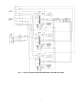
VIA CC REV PP VIB II F FM RST R CC CC S1 S2 S3 CC OUT P24 P24 IV ISOLATOR + - LEGEND TYPICAL FACTORY WIRING OPTIONAL FIELD WIRING Fig. 15 — VFD (S9 Inverter) Interface Wiring and Jumpers P24 RES ST FM RR AM S1 R F CC CC S2 S3 RX CC CC PP S4 IV RCH FP FLC P24 IV P24 LOW LOW A C FLB FLA I 5 V 10 SW1 SETTING FOR 4-20mA OPERATION, SWITCH LOCATED ON VFD CONTROL BOARD ISOLATOR + - Fig.
Table 8 — VFD (S9 Inverter) Terminal Designations TERMINAL L1 (R) L2(S) L3(T) T1(U) T2(V) T3(W) R C II (+) CC(–) P24 (+) II (–) S3 CC(–) S2 CC(–) SI CC(–) Table 9 — VFD (E3 Inverter) Terminal Designations FUNCTION Three-Phase Main Circuit Input Power Supply. TERMINAL L1 (R) L2(S) L3(T) T1(U) T2(V) T3(W) CC ST R CC S4 CC S1 CC P24 IV Three-Phase AC Output to Motor 0 V to Maximum Input Voltage Level Configured to auto start motor in the reverse direction as required by fan/motor configuration.
chrome vinyl, or Teflon with a minimum operating temperature range of –20 C to 60 C is required. It is important when connecting to a CCN communication bus that a color-coding scheme be used for the entire network to simplify the installation. It is recommended that red be used for the signal positive, black for the signal negative and white for the signal ground. Use a similar scheme for cables containing different colored wires.
Table 10 — Field Connection Terminal Strips TERMINAL TERMINAL DESCRIPTION BOARD NO.
CCN BUS ROOFTOP UNIT ROOFTOP UNIT CL CL COMPUTER WITH COMPUTER WITH ComfortVIEW™ ComfortView™ SOFTWARE SOFTWARE CCN WEB OR NETWORK OPTIONS ROOFTOP UNIT ROOFTOP UNIT CL CL HEATING/COOLING UNITS REMOTE CCN SITE TELINK BRIDGE (RECOMMENDED) TO ADDITIONAL TERMINALS CL CID ROOFTOP UNIT COMFORT ID AIR TERMINAL CID CID COMFORT ID AIR TERMINAL NON CARRIER HVAC EQUIPMENT COMFORT CONTROLLER CCN CID CL HVAC — — — — AIR DISTRIBUTION-DIGITAL AIR VOLUME CONTROL (DAV) LEGEND Carrier Comfort Network C
CONTROL FUNCTIONS • Daylight Savings Time function. • Occupancy control with 8 periods for unit operation. • Holiday Table containing up to 30 holidays within the control. • Ability to initiate timed override from T55, T56 and T58 devices. • Ability to use multiple space temperature sensors (T55 only) to average Space Temperature external to the control. • Ability to support the CCN communicating T58 sensor. • Factory Test for end of production line tests.
Scrolling Marquee Display Operation — The key to the setup, operation, and diagnostics for the 48/50A series ComfortLink™ Control System is the Scrolling Marquee display. All units are shipped from the factory with the Scrolling Marquee display, which is located in the main control box. See Fig. 14. In addition, the ComfortLink control also supports the use of the hand held Navigator which can be plugged into the J11 jack in the main control box on TB3.
Table 11 — Scrolling Marquee Menu Display Structure RUN SERVICE TEMPERAPRESSURES STATUS TEST TURES Auto View Software Unit Circuit of Command Temperatures Pressures Run Status Disable (UNIT) (CIRC) (VIEW) (STOP) Software Service Test Circuit Air Pressure Version Mode Temperatures (AIR) Numbers (TEST) (CIRC) (VERS) Cir and Comp Test Calibrate Calibrate Run Hours Independent Temperatures Pressures (HRS) Outputs (CAL) (CAL) (INDP) Compressor Test Fans Starts (FANS) (STRT) TimeGuards (TMGD) Test Cooling (COOL)
ENTER ENTER TEXT TEXT TEXT TEXT NAVI SCB CEM MARQ — — — — — — — — — — MARQ CEM SCB NAVI ECB2 ECB1 TEXT — ECB2 — TEXT ECB1 — MBB — CESR131171-XX-XX CESR13174-XX-XX CESR131226-XX-XX CESR131227-XX-XX CESR131249-XX-XX CESR131249-XX-XX CESR131343-XX-XX Software Version Number Indicates the software that has been loaded.
TMGD STRT HRS ENTER ENTER ENTER SUBMODE KEYPAD ENTRY XXXX XXXX XXXX XXXX XXXX XXXX XXXX XXXX XXXX TG.B1 TG.B2 TG.H1 YG.H2 YG.H3 TG.H4 TG.H5 TG.H6 XXXX ST.B2 TG.A2 XXXX ST.B1 XXXX XXXX ST.A2 TG.
TEXT TEXT TEXT TEXT TEXT PE.B PE.C H.I.R. ALR TEXT TEXT HS.6 — — — — — OFF/ON OFF/ON OFF/ON Heat Stage 6 Heat Stage 5 Heat Stage 4 Heat Stage 3 Heat Stage 2 HS.5 — OFF/ON OFF/ON TEXT — — HS.4 — — TEXT Compressor B2 Relay HS.3 OFF/ON OFF/ON Compressor B1 Relay TEXT — — OFF/ON HS.
ENTER CIRC XXX.X XXX.X XXX.X XXX.X XXX.X XXX.X XXX.X XXX.X XXX.X RAT MAT EDT LAT SPT SPTO LAT.1 LAT.2 LAT.3 XXX.X XXX.X CTB.T F F C C C 0 0 0 0 0 0 0 –30 to 30 –30 to 30 –30 to 30 –10 to 10 Condensing Temp B Trim Condensing Temp A Trim Staged Gas LAT Avg Trim Space Temp Trim SAT Trim RAT Trim CTA.T F 0 –10 to 10 –10 to 10 XXX.X C 0 0 SGT.T F 0 0 XXX.X C C SPT.T F F calculated from suction pressure Used for calibration of average SGT.
CAL AIR CIRC SUBMODE ENTER ENTER ENTER KEYPAD ENTRY pa in-H2O 0 0 0 0 –50 to 50 Suction Pressure B Trim –50 to 50 Suction Pressure A Trim –10 to 10 Building Pressure Trim X.X 0 0 SPBT pa in-H2O pa X.X in-H2O SPAT BP PID/Integral Term X.XX NA BP Load Factor Building Pressure Duct Static Pressure BP.T 0 NA NA –2 to 2 0-5 Air Pressures Cir B Discharge Pressure –10 to 10 Static Pressure Trim 0 NA NA NA NA 0-500 X.
ENTER ENTER ENTER ENTER ENTER BP.SP SA.SP SA.SH HI.SA LO.SA ENTER GAP ENTER ENTER HEAT SP.SP ENTER KEYPAD ENTRY COOL SUBMODE XX.X V.C.OF LO.SA HI.SA SA.SH SA.SP BP.SP SP.SP GAP XX XX XXX XX.X X.XX X.X X.X XX.X XX.X V.C.ON UHSP XX.X NT.LO XX.X XX.X UCSP OHSP XX.X DISPLAY OCSP ITEM F F F F H2O H2O F F F F F F F F C C C C Pa Pa C C C C C C C C UNITS English Metric 65.0 55.0 125.0 55.0 0.05 1.5 5.0 55.0 68.0 2.0 72.
SW.IN STAT SUBMODE ENTER ENTER KEYPAD ENTRY TEXT TEXT TEXT TEXT TEXT TEXT TEXT TEXT TEXT FDWN F.PRS F.EVC F.PRG E.ENA E.OVR RE.MT DLM.1 DLM.2 TEXT GAS.F — — — — — — — — — — TEXT FAN.S — — TEXT G — TEXT TEXT W2 — FIL.S TEXT W1 — — TEXT Y2 — — — — — — — — — — — — — — — — — — UNITS English Metric SW.
ENTER ENTER MISC ENTER AQ.IN CS.IN KEYPAD ENTRY SUBMODE TEXT % % 0-20 0-100 4-20 mA remote input Used for remote min position and remote economizer position control Miscellaneous inputs Status of compressor A1 feedback signal Status of compressor A1 feedback signal Status of compressor A1 feedback signal Status of compressor A1 feedback signal Compressor feedback digital inputs Calculated from RAT and RA.
KEYPAD ENTRY ENTER ENTER SUBMODE FANS CMPR TEXT TEXT TEXT TEXT MLV B1 B2 TEXT OFC.B A2 TEXT OFC.A TEXT XXX S.VFD A1 TEXT DISPLAY S.
KEYPAD ENTRY ENTER ENTER SUBMODE HEAT ECONO TEXT TEXT TEXT TEXT TEXT HS.3 HS.4 HS.5 HS.6 HIR XXX TEXT TEXT TEXT TEXT EC.CP E.PWR PE.A PE.B PE.C XXX TEXT HS.2 EC.AP TEXT DISPLAY HS.
ENTER ENTER KEYPAD ENTRY X FAN.M TEXT TEXT TEXT B1.C.E B2.C.E TEXT B1.EN A2.C.E — TEXT A2.EN TEXT TEXT A1.EN TEXT X.X Z.GN B2.EN XX C.TC.F A1.C.E — XX C.FOD F CLOA — — — — — — — MIN SEC F XXX.X XXX.X HP.SP — SEC X — — — — COOL XXX TEXT DP.XR SAMP TEXT R.MAT MIN XX TEXT TEXT — TEXT IF.IS S.MM DELY — X IF.M MAT.S — TEXT — VS.
XX XX XX XX.X XX XX E.FOD G.FOD H.T.CF S.CP.M S.PI.R S.RIS F C 50 50 50 50 -20 TO 80 -20 TO 80 -20 TO 80 Tempering Purge SASP Tempr Vent Unocc SASP Tempering Vent OCC SASP XX C 65 T.PRG F 65 XX C -20 TO 40.0 Derivative Gain T.VU F 40 0 TO 1.5 Proportional Gain Integral Gain XX 40 1 0 TO 1.5 0 TO 1.5 ST.Gas Temp. Dead Band S. Gas DB Min.
ENTER KEYPAD ENTRY X XXX TEXT XX.X X X XXX XXX UFC.C UFC.T TRM.E EC.CB PWRX PWRM PE1.P PE2.P XXX.X OA.DL XXX.X X OA.EC OEN.C XXX.X OAT.L % % — — F — MIN — Btu/lb F — F % % % — — C — MIN — kcal/kg C — C % 75 35 4 none 2 Enabled 120 0 27 55 CURVE B 60 20 75 35 4 none 2 Enabled 120 0 27 55 CURVE B 60 20 Outdr.
BP SVFD SUBMODE ENTER ENTER KEYPAD ENTRY X.X X.X X.X XX X.XX SP.KD SP.KI SP.K SP.DT SP.H.L X TEXT X.XX XX.X XX X.XXX X.XXX BP.SL BP.S BP.R BP.ZG BP.DT BP.HP BP.LP X.XX XX.X SP.KP SP.L.L XXX SF.FS in-H2O in-H2O MIN — in-H2O — — in-H2O in-H2O sec — — — — % % cm-H2O cm-H2O — cm-H2O — — cm-H2O cm-H2O sec — — — — % % 0.04 0.05 1 1 0.25 DSBL 2 0 5 2 1 2 0 20 100 100 20 0.04 0.05 1 1 0.
KEYPAD ENTRY ENTER SUBMODE IAQ MIN % X X XXX XXX TEXT XX XXX XXX XXX X XXXX XXXX XXXX XXXX XXX XXX XXXX XXXX XXXX XXXX XXX IA.I.C IA.I.F AQ.MP MIN.I PRG.E PRG.D PG.LT PG.HT OVR.P OA.CF OAQ.U OAQ.L AQD.L AQD.H DF.ON DF.OF I.4M I.20M O.4M O.20M I.CRV ppm ppm ppm ppm ppm ppm ppm ppm ppm ppm — — % % — % % — — — X IA.
RST CMF.D OPTS SUBMODE ENTER ENTER ENTER KEYPAD ENTRY TEXT X TEXT TEXT TEXT X STO.S STO.R R.RH.S O.RH.S DMT.S RMT.C XXX.X XXX.X XXX.X XXX.X XX XXX.X XX LH.ON LH.OF HH.ON CT.LV CT.TM HT.LV HT.TM X X.X XX.X RST.T RTIO R.LIM RST XXX.X XXX.X LC.OF HC.ON XXX.X LC.ON TEXT TEXT F — — sec F sec F F F F F F F — — — — F — — C — — sec C sec C C C C C C C — — — — C — — — 10 3 NONE 60 0.1 60 0.1 0.5 1 1.5 0.5 1 1.
CCN DMD.L SUBMODE ENTER ENTER KEYPAD ENTRY 1 50 1 50 80 1 TO 239 0 to 100 0 to 100 0 TO 120 Demand Limit SW.2 Setpt Demand Limit SW.1 Setpt Maximum Loadshed Time Loadshed Demand Delta TEXT TEXT TEXT TEXT TEXT TEXT B.TIM B.OAT B.ORH B.OAQ B.GS B.
SW.LG DISP SUBMODE ENTER ENTER KEYPAD ENTRY TEXT TEXT TEXT TEXT TEXT TEXT TEXT FTS.L FSD.L IAQ.L PRS.L PRG.L PMI.L SFS.L OPEN OPEN OPEN OPEN OPEN OPEN OPEN OPEN OPEN OPEN OPEN OPEN OPEN OPEN OPEN OPEN OPEN OPEN OPEN OPEN OPEN/CLSE OPEN/CLSE OPEN/CLSE OPEN/CLSE OPEN/CLSE OPEN/CLSE OPEN/CLSE OPEN/CLSE OPEN/CLSE OPEN/CLSE Fan Status SW. Normally: Remote Switch Normally: Smoke Purge SW. Normally: Press. Switch Normally: IAQ Disc.
ALLM SUBMODE ENTER KEYPAD ENTRY X.XX X.XX X.XX XXX BP.L BP.H IQ.HI XXX.X RAH.U DP.H XXX.X RAL.U X.XX XXX.X RAH.O DP.L XXX.X RAL.O XXX XXX.X SAH.U IRH.H XXX.X SAL.U XXX XXX.X SAH.O IRH.L XXX.X ppm H2O H2O H2O H2O % % F F F F F F F F ppm pa pa pa pa % % C C C C C C C C C 800 0.25 -0.25 2 0 100 0 120.0 35.0 90.0 60.0 180.0 45.0 180.0 45.0 100.0 800 0.25 -0.25 2 0 100 0 120.0 35.0 90.0 60.0 180.0 45.0 180.0 45.
ENTER ENTER ENTER ENTER OVR.S OVR.T OVR.G OTL ENTER ENTER DST SCH.N ENTER DATE KEYPAD ENTRY ENTER SUBMODE TIME SUBMODE XX XX STP.D M.SUB OTL OVR.G OVR.T OVR.S X TEXT TEXT TEXT XX XX STP.W SCHN XX STP.M hrs — — — — min day week month min 1 NO YES YES 0 60 7 5 10 60 1 NO YES YES 0 60 7 5 10 60 7 1-24 YES/NO YES/NO YES/NO 1-99 0-1440 1-7 1-52 1-12 0-1440 1-7 Override Time Limit Global Sched.
SCH.L SUBMODE PER.2 PER.1 SUBMODE ENTER TEXT TEXT TEXT TEXT TEXT TEXT THU.2 FRI.2 SAT.2 SUN.2 HOL.2 TEXT HOL.1 WED.2 TEXT SUN.1 TEXT TEXT SAT.1 TUE.2 TEXT FRI.1 TEXT TEXT THU.1 MON.2 TEXT WED.1 XX:XX TEXT TUE.1 UNC.2 TEXT MON.1 XX:XX XX:XX UNC.1 OCC.2 XX:XX OCC.1 -— — — — — — — — time time — — — — — — — — time time NO NO NO NO NO NO NO NO 00.00 00.00 NO NO NO NO NO NO NO NO 00.00 00.00 NO NO NO NO NO NO NO NO 00.
SCH.L (cont) SUBMODE PER.4 PER.3 SUBMODE ENTER TEXT TEXT TEXT TEXT TEXT TEXT THU.4 FRI.4 SAT.4 SUN.4 HOL.4 TEXT HOL.3 WED.4 TEXT SUN.3 TEXT TEXT SAT.3 TUE.4 TEXT FRI.3 TEXT TEXT THU.3 MON.4 TEXT WED.3 XX:XX TEXT TUE.3 UNC.4 TEXT MON.3 XX:XX XX:XX UNC.3 OCC.4 XX:XX OCC.3 -— — — — — — — — time time — — — — — — — — time time NO NO NO NO NO NO NO NO 00.00 00.00 NO NO NO NO NO NO NO NO 00.00 00.
SCH.L (cont) SUBMODE PER.6 PER.5 SUBMODE ENTER TEXT TEXT TEXT TEXT TEXT TEXT THU.6 FRI.6 SAT.6 SUN.6 HOL.6 TEXT HOL.5 WED.6 TEXT SUN.5 TEXT TEXT SAT.5 TUE.6 TEXT FRI.5 TEXT TEXT THU.5 MON.6 TEXT WED.5 XX:XX TEXT TUE.5 UNC.6 TEXT MON.5 XX:XX XX:XX UNC.5 OCC.6 XX:XX OCC.5 -— — — — — — — — time time — — — — — — — — time time NO NO NO NO NO NO NO NO 00.00 00.00 NO NO NO NO NO NO NO NO 00.00 00.
SCH.L (cont) SUBMODE PER.8 PER.7 SUBMODE ENTER TEXT TEXT TEXT TEXT TEXT TEXT THU.8 FRI.8 SAT.8 SUN.8 HOL.8 TEXT HOL.7 WED.8 TEXT SUN.7 TEXT TEXT SAT.7 TUE.8 TEXT FRI.7 TEXT TEXT THU.7 MON.8 TEXT WED.7 XX:XX TEXT TUE.7 UNC.8 TEXT MON.7 XX:XX XX:XX UNC.7 OCC.8 XX:XX OCC.7 -— — — — — — — — time time — — — — — — — — time time NO NO NO NO NO NO NO NO 00.00 00.00 NO NO NO NO NO NO NO NO 00.00 00.
HOL.6 HOL.5 HOL.4 HOL.3 HOL.2 HOL.1 ESCAPE ENTER ESCAPE ENTER ESCAPE ENTER ESCAPE ENTER ESCAPE ENTER ESCAPE XX LEN.1 X XX DAY.6 LEN.6 XX XX LEN.5 MTH.6 X DAY.5 XX XX LEN.4 MTH.5 X DAY.4 XX XX LEN.3 MTH.4 X DAY.3 XX XX LEN.2 MTH.3 X DAY.2 XX X DAY.1 MTH.2 XX MTH.
HOL.L (cont) HOL.G SUBMODE HOL.9 HOL.8 HOL.7 SUBMODE ESCAPE ENTER ESCAPE ENTER ESCAPE ENTER ENTER KEYPAD ENTRY X XX DAY.9 LEN.9 XX XX LEN.8 MTH.9 X DAY.8 XX XX LEN.7 MTH.8 X XX TEXT DISPLAY DAY.7 MTH.7 HOL.
Table 21 — Operating Mode Display Menu SUBMODE KEYPAD ENTRY ITEM DISPLAY ENTER MODE MODE Modes Controlling Unit COOL COOL Cool Mode Cooling Mode in effect HEAT HEAT Heat Mode Heating Mode in effect VENT VENT Vent Mode Unit is between heating and cooling mode limits TMPR TMPR Supply Air Tempering OCC OCC T.OVR MODE ITEM EXPANSION COMMENTS Currently Occupied unit in occupied mode T.OVR Timed Override in Effect unit operating under timed override A.DCV A.
Modes — The system mode is the highest level mode and SYSTEM MODE — TEST — When the system mode is Test, the software application in the control is constrained to the Test mode and is controllable via the local displays (Scrolling Marquee and Navigator) or through the factory service test control. See the Test Mode section for details on test control in this mode.
General Heating and Cooling Run Control — For normal comfort conditioning there are three basic modes. These are: • HEAT — Air is warmed by electric or gas heat. There are actually two modes under heat which are Low Heat (Mode 6 — HVAC_HEAT) and High Heat (Mode 7 — HVAC_HTHI). • VENT — No cooling or heating is activated and just outside air is introduced into the conditioned space to control Indoor Air Quality. This is the vent mode (Mode 2 — HVAC_VENT).
• DMD Level Lo Heat On (LH.ON) — This is the low heating differential demand enable set point temperature. It is the space temperature differential below the heating set point which will enable low heating demand. It is configured in CONFIGURATION-CMF.D submenu. • DMD Level (–) Low Heat Off (LH.OF) — This is the low heating differential demand disable set point temperature. It is the space temperature differential below the heating set point which will turn off low heating demand.
(SAMP), which can reschedule a re-sampling of the airstream. This feature will result in the supply fan turning on during unoccupied periods. The temperatures and configuration items that are used are listed below. Temperatures • Space Sensor Temperature (SPT) — This is the temperature measured by the T55 sensor. It is used in the unoccupied mode to initiate operation. This can be read in the TEMPERATURE-UNIT submenu.
The set points that are used for tempering are listed below. • Tempering in Cool Supply Air Set Point (SASP) (T.CL) — This is used when the unit is in cooling mode and the economizer is at the minimum position. Tempering will add heat if the temperature is below the set point. • Tempering Vent OCC SASP (T.VO) — This is the temperature set point that will be used for tempering during the Vent mode while in occupied mode. • Tempering Vent Unocc SASP (T.
Normally this control logic will not require any tuning or adjust other than to select the temperature control set points. If there is an application where the unit may be significantly oversized and there are indications of high compressor cycles then the Capacity Threshold Adjust (Z.GN) can be used to adjust the overall logic gain. Normally this is set to 1.0, but it can be adjusted from 0.5 to 4.0. As the number is increased the responsiveness of the logic will be slowed.
Table 25 — Staging Sequence Without Hot Gas Bypass — 48/50AK,AY020-027 and Multi-Stage 48/50AJ,AW STAGE SEQUENCE 1 2 3 Compressor Status ON ON OFF OFF ON ON OFF OFF ON Unit Capacity 48/50A 33% 67% 67% 30% 65% 70% 33% 67% 67% 0 1 COMP A1 A2 B1 OFF OFF OFF 20 25 27 0% 0% 0% 4 0 ON ON ON OFF OFF OFF 100% 100% 100% 0% 0% 0% SEQUENCE 2 2 3 Compressor Status OFF ON ON ON ON OFF OFF OFF ON Unit Capacity 48/50A 33% 67% 67% 35% 65% 65% 33% 67% 67% 1 4 ON ON ON 100% 100% 100% Table 26 — Staging Sequen
Compressor Safeties — The 48/50A series units with • (1) SWITCH — This will enable the switch input demand limit using the switch inputs connected the CEM board. Connections should be made to TB6 terminals 4, 5, and 6. • (2) 4-20MA — This will enable the use of a remote 4 to 20 mA demand limit signal. The CEM module must be used. The 4 to 20mA signal must come from an externally sourced controller and should be connected to TB6 terminals 9 and 10.
Head Pressure Control — The condenser head pres- difference is during unoccupied mode, when the determination to bring on the supply fan is based on space temperature or return air temperature. In addition to the normal demand driven logic there are also some overrides based on evaporator discharge temperature.
The first two staged gas heat outputs are located on the MBB board and outputs 3, 4, 5, and 6 are located on the SCB board. These outputs are used to determine the number of stages (5 to 11) as shown in Tables 31-34. have not ignited then heating is locked out. The control will reset when the request for W (heat) is temporarily removed. When ignition occurs, the IGC board will continue to monitor the condition of the rollout switch, limit switches, Hall Effect Sensor, and the flame sensor.
Table 32 — Staged Gas Heat Control Steps (N.
An LED indicator is provided on the IGC to monitor operation. The IGC boards are located in the gas heat section below the indoor fans. During normal operation the LED is continuously on. Table 35 shows the error codes. point for the outdoor air upper limit can be configured in the CONFIGURATION-ECON submenu using the High OAT Lockout Temp (OAT.L) setting.
Fig. 24 — Enthalpy Changeover Curves Fig.
RETURN AIR RH SENSOR (R.RH.S) — This is located in the CONFIGURATION-OPTS submenu and is used to enable and disable the use of the return air humidity sensor. OUTSIDE AIR RH SENSOR (O.RH.S) — This is located in the CONFIGURATION-OPTS submenu and is used to enable and disable the use of the outside air humidity sensor. ECONOMIZER SWITCH NORMALLY (EC.SL) — This is located in the CONFIGURATION-SW.LG submenu and is used to configure the normally open and closed status of the switch.
IAQ Control — The ComfortLink™ control has the capability of demand ventilation control using an IAQ sensor. The indoor air quality (IAQ) is measured using a CO2 sensor whose measurements are displayed in parts per million (PPM). The IAQ sensor can be field-installed or factory-installed in the return duct. If IAQ must be measured directly in the space instead of the unit return duct, a wall-mounted accessory can be field installed. The sensor must be 4 to 20 mA and must be include a 24-V supply.
IAQ DEMAND VENT MIN POS. (AQ.MP) — This configuration will be used to set the minimum damper position in the occupied period when there is no IAQ demand. ECONOMIZER MIN POSITION (MIN.P) — This is the fully occupied minimum economizer position. It is configured in the CONFIGURATION-ECON submenu. IAQ PURGE (PRG.E) — This is used to enable IAQ preoccupancy purge. IAQ PURGE DURATION (PRG.D) — This is the configurable time that will be used to turn on purge prior to occupancy. IAQ PURGE LO TEMP MIN POS (PG.
Pre-Occupancy Purge — The control has the option Static Pressure Control — The control supports the for a pre-occupancy purge to clear the space prior to occupancy. The feature is enabled by the PRG.E variable which is located in the CONFIGURATION-IAQ submenu. The IAQ Purge will operate under the following conditions: • PRG.
Table 38 — VFD (E3 Inverter) Configurations SetP ACC1 DEC1 UL LL lulu P3 F-P3 P4 F-P4 tHr1 StC1 StL1 OLN tYP Gr.F FH UL pt GR.Fb FbP1 Fbln GP Gl GA GFS P1LL PuL PuU1 PuLL SETUP PARAMETERS 60.0 sec 60.0 sec 60.0 Hz 0 Hz 1 20% 0.0 Hz 100% 60 Hz — 0 110% 1 5 FUNDAMENTAL PARAMETERS 60Hz* 60Hz 2 FEEDBACK PARAMETERS 0* 2 0.3 2 sec 0 0 80 10 1 10 10 GR.SF Fsor Gr.Pn Fr FGr.St lt lt0 lt1 lt2 lt3 lt4 GGr.Pr UuC UuCt ArSt Gr.Ut Cnod Fnod bLPn FREQ.
The rooftop unit has the design static pressure set point programmed into the CCN control. This is the maximum set point that could ever be achieved under any condition. To simplify the installation and commissioning process for the field, this system control is designed so that the installer only needs to enter a maximum duct design pressure or maximum equipment pressure, whichever is less.
The following configurations are required for this logic: TCST COOL TIME/TEMP FACT (C.TC.F) — This is located in the CONFIGURATION-COOL submenu and is the factor for the start time bias equation for cooling. TCST HEAT TIME/TEMP FACT (H.TC.F) — This is located in the CONFIGURATION-HEAT submenu and is the factor for the start time bias equation for heating. BUILDING PRESSURE SENSOR HIGH END (BPHL) — This is used to configure the building pressure value that will correspond to a 20 mA signal from the sensor.
IAQ DISC. INPUT NORMALLY (IAQ.L) — This is located in the CONFIGURATION-SW.LG submenu and is used to configure the normally open/closed status of the switch. PRESS. SWITCH NORMALLY (PRS.L) — This is located in the CONFIGURATION-SW.LG submenu and is used to configure the normally open/closed status of the switch. SMOKE PURGE SW. NORMALLY (PRG.L) — This is located in the CONFIGURATION-SW.LG submenu and is used to configure the normally open/closed status of the switch.
Table 41 — Alert and Alarm Codes ALARM OR ALERT NUMBER A051 DESCRIPTION A051 Circuit A, Compressor 1 Current Detected After Shutdown ACTION TAKEN BY CONTROL Turn off all compressors P051 Compressor A1 Safety Trip Add strike to Compressor T051 A052 Circuit A, Compressor 1 Failure Circuit A, Compressor 2 Current Detected After Shutdown P052 Circuit A, Compressor 2 Failure Add strike to Compressor T052 A055 Circuit A, Compressor 2 Failure Circuit B, Compressor 1 Current Detected After Shutdown Co
Table 41 — Alert and Alarm Codes (cont) ALARM OR ALERT NUMBER DESCRIPTION ACTION TAKEN BY CONTROL RESET METHOD Stop gas heat Automatic Control Board failure, check lights Stop options on CEM Automatic Control Board failure, check lights Stop economizer & power exh Stop unit Stop demand limiting Stop unit Close economizer, stop exhaust Stop unit Stop IAQ control Use a default value for IAQ Use software configured minimum not used at this time not used at this time not used at this time Stop cooling
3. Check for welded contactor. 4. Verify CS wiring. 5. Return to Normal mode and observe compressor operation to verify that compressor current sensor is working and condenser fans are energized after compressor starts. Alert Codes 64, and 65 (Condensing Temp. Failure) — Alert codes 64, and 65 are for circuits A and B respectively. These alerts occur when the saturated condensing temperatures (SCT.A and SCT.B) are outside the range –40 to 240 F (–40 to 116 C).
off. This will require a manual reset through the Scrolling Marquee display. Alarm Code 150 (Unit in Emergency Stop) — If the fire safety input condition occurs to indicate a fire or smoke condition, then Alarm code 150 will occur and the unit will be immediately stopped. Through separate inputs the unit can be put into purge, evacuation, and pressurization. This requires a manual reset.
routines will be modified. The unit will continue to run but VAV heating will be disabled. The limits are configurable and are located in the CONFIGURATION-ALLM submenu. Alert 305 (Return Air Temperature Above Limit) — If the return air temperature is below the RAT HI Alert Limit/Occ (RAH.O) OR RAT HI Alert Limit/Occ (RAH.U), then the unit will continue to run but the alert will be indicated. The alert will automatically reset. The limits are configurable and are located in the CONFIGURATION-ALLM submenu.
clockwise position and the actuator should be mounted so that the CW face of the actuator is accessible. Correct if necessary. This alert clears automatically. Alert Code 414 (Belimo Actuator Failure) — This alert occurs when the commanded damper position is changing too rapidly. This alert resets automatically. Alert Code 414 (Belimo Actuator Hunting Alert) — This alert occurs when there is excess movement of the economizer motor. Check the mechanical actuation of the dampers. .
6. Under the CONFIGURATION-UNIT submenu, set FAN.M to 1 for continuous fan or 0 for automatic fan. Most building codes now require continuous fan for ventilation. 7. To program local time schedules, set SCH.N=1 under the TIMECLOCK menu to configure the control to use local schedules. 8. Under the TIMECLOCK-SCH.L submenu, enter the desired schedule. See Table 20 for further descriptions of these configurations. 9.
3. The space temperature set points and the supply air set points are configured under the SETPOINTS menu. The heating and cooling set points must be configured. See the General Heating and Cooling Control section for further description on these configurations. Configure the following set points: OHSP Occupied Heat Set Point OCSP Occupied Cool Set Point UHSP Unoccupied Heat Set Point UCSP Unoccupied Cool Set Point GAP Heat-Cool Set Point Gap SA.SP Supply Air Set Point SA.HT Heating Supply Air Set Point V.
PWRM Power Exhaust motors should be set to 1 (4 motors) for the 020-050 units and 2 (6 motors) for the 060 unit In the CONFIGURATION-BP submenu set the following variables: BP.SL Modulating PE Alg Select to 2 BP.S Building Pressure sensor to enable BP.R Building pressure sensor range to 0.25 BP.HP High BP level to desired value BP.LP Low BP level to the desired value If a remote switch option is being used and configured for start/stop, then the switch must be closed for the unit to operate.
For units with 2 stage gas heat control, the MBB is powered by 24 VAC. When the thermostat or room sensor calls for heating as determined by the MBB, the MBB will close heating relays and send power to W on each of the IGC boards (2 on sizes 020-050 and 3 on size 060). An LED on the IGC board will be on during normal operation. A check is made to ensure that the rollout switches and limit switches are closed and the induced-draft motors are not running.
Unit Preparation — Check that unit has been installed in accordance with the installation instructions and applicable codes. Heating, ventilation and air conditioning (HVAC) and other building equipment being controlled by ComfortLink™, PICs, or Comfort Controller Devices have the inherent ability to ‘talk’ on a common communications bus or network.
Table 42 — Fan Performance — 48AJ,AK020,025 Units 48AJ,AK020,025 (20 THRU 25 TONS) Cfm 4,000 5,000 6,000 7,000 7,500 8,000 9,000 10,000 11,000 12,000 12,500 13,000 0.2 Rpm Bhp 394 1.06 388 1.26 427 1.76 476 2.44 502 2.83 527 3.26 580 4.25 633 5.40 687 6.74 741 8.26 768 9.10 796 9.98 0.4 Rpm 413 448 489 534 557 580 629 679 731 783 809 835 Bhp 1.15 1.58 2.15 2.86 3.27 3.72 4.74 5.93 7.30 8.86 9.71 10.62 0.6 Rpm 478 509 544 584 606 628 674 721 770 820 846 871 Bhp 1.51 1.96 2.54 3.28 3.70 4.16 5.21 6.43 7.
Table 44 — Fan Performance — 48AJ,AK035 Units 48AJ,AK035 (35 TONS) Cfm 7,000 8,000 9,000 10,000 10,500 11,000 12,000 13,000 14,000 15,000 16,000 17,000 17,500 0.2 Rpm Bhp 549 2.97 606 3.95 664 5.11 723 6.46 753 7.22 783 8.02 843 9.79 903 11.78 964 14.00 1025 16.46 1086 19.17 1147 22.13 1177 23.71 0.4 Rpm Bhp 598 3.40 651 4.40 706 5.58 762 6.96 790 7.73 819 8.55 877 10.34 935 12.35 994 14.60 1053 17.08 1112 19.81 1172 22.80 1202 24.39 0.6 Rpm Bhp 644 3.83 694 4.85 745 6.06 799 7.46 826 8.24 853 9.
Table 46 — Fan Performance — 48AJ,AK050 Units 48AJ,AK050 (50 TONS) Cfm 8,000 9,000 10,000 11,000 12,000 13,000 14,000 15,000 16,000 17,000 18,000 19,000 20,000 0.2 Rpm Bhp 512 2.98 561 3.90 611 5.00 662 6.27 714 7.74 766 9.41 819 11.29 872 13.40 925 15.74 979 18.32 1032 21.15 1086 24.24 1140 27.60 0.4 Rpm Bhp 560 3.38 604 4.33 651 5.45 699 6.75 748 8.24 798 9.93 848 11.84 899 13.96 951 16.32 1003 18.92 1055 21.77 1108 24.88 1161 28.25 0.6 Rpm Bhp 604 3.79 645 4.77 689 5.91 734 7.23 780 8.75 828 10.
Table 48 — Fan Performance — 50AJ,AK020,025 Units 50AJ,AK020,25 (20 THRU 25 TONS) Cfm 4,000 5,000 6,000 7,000 7,500 8,000 9,000 10,000 11,000 12,000 12,500 13,000 0.2 Rpm Bhp 394 1.06 388 1.26 398 1.59 441 2.18 463 2.52 486 2.90 532 3.76 579 4.76 627 5.91 675 7.23 699 7.96 724 8.72 0.4 Rpm Bhp 398 1.08 428 1.47 463 1.97 501 2.60 521 2.96 542 3.36 585 4.26 629 5.30 674 6.50 720 7.86 743 8.60 767 9.39 0.6 Rpm 464 489 520 554 572 591 631 673 716 760 782 805 Bhp 1.42 1.83 2.36 3.02 3.39 3.80 4.73 5.81 7.
Table 50 — Fan Performance — 50AJ,AK035 Units 50AJ,AK035 (35 TONS) Cfm 7,000 8,000 9,000 10,000 10,500 11,000 12,000 13,000 14,000 15,000 16,000 17,000 17,500 0.2 Rpm Bhp 517 2.72 569 3.59 622 4.63 675 5.84 702 6.51 729 7.23 784 8.80 839 10.57 894 12.54 949 14.73 1005 17.13 1061 19.76 1088 21.16 0.4 Rpm Bhp 568 3.14 616 4.04 665 5.10 716 6.34 741 7.02 767 7.75 819 9.35 872 11.15 925 13.15 979 15.36 1033 17.78 1088 20.43 1115 21.84 0.6 Rpm Bhp 616 3.56 660 4.49 706 5.58 754 6.84 778 7.53 803 8.27 853 9.
Table 52 — Fan Performance — 50AJ,AK050 Units 50AJ,AK050 (50 TONS) Cfm 8,000 9,000 10,000 11,000 12,000 13,000 14,000 15,000 16,000 17,000 18,000 19,000 20,000 0.2 Rpm Bhp 485 2.76 530 3.62 577 4.62 625 5.80 673 7.15 722 8.69 771 10.43 821 12.37 870 14.52 920 16.89 971 19.50 1021 22.35 1071 25.43 0.4 Rpm Bhp 532 3.15 574 4.03 617 5.06 661 6.26 707 7.63 753 9.19 800 10.95 848 12.91 896 15.08 945 17.48 994 20.10 1043 22.96 1092 26.07 0.6 Rpm Bhp 577 3.54 615 4.45 655 5.50 697 6.73 740 8.12 784 9.70 829 11.
Table 54 — Fan Performance — 48AW,AY020,025 Units 48AW,AY020,025 (20 THRU 25 TONS) Cfm 4,000 5,000 6,000 7,000 7,500 8,000 9,000 10,000 11,000 12,000 12,500 13,000 0.2 Rpm Bhp 394 1.06 394 1.29 445 1.87 498 2.59 526 3.02 554 3.48 610 4.55 668 5.80 727 7.25 786 8.90 816 9.81 846 10.77 0.4 Rpm Bhp 422 1.20 461 1.66 505 2.26 553 3.01 578 3.45 604 3.93 657 5.03 711 6.31 766 7.79 823 9.48 852 10.40 880 11.38 0.6 Rpm Bhp 486 1.56 520 2.04 559 2.66 603 3.44 626 3.89 650 4.38 699 5.51 751 6.82 804 8.32 858 10.
Table 56 — Fan Performance — 48AW,AY035 Units) 48AW,AY035 (35 TONS) Cfm 7,000 8,000 9,000 10,000 10,500 11,000 12,000 13,000 14,000 15,000 16,000 17,000 17,500 0.2 Rpm Bhp 568 3.13 629 4.17 690 5.40 753 6.85 784 7.65 816 8.50 879 10.39 943 12.51 1007 14.89 1072 17.52 1136 20.41 1201 23.58 1233 25.27 0.4 Rpm Bhp 616 3.56 673 4.62 731 5.88 790 7.35 820 8.16 851 9.03 912 10.94 973 13.09 1036 15.48 1098 18.13 1162 21.05 1225 24.24 1257 25.94 0.6 Rpm Bhp 661 4.00 714 5.08 769 6.36 826 7.85 855 8.68 884 9.
Table 58 — Fan Performance — 48AW,AY050 Units 48AW,AY050 (50 TONS) Cfm 8,000 9,000 10,000 11,000 12,000 13,000 14,000 15,000 16,000 17,000 18,000 19,000 20,000 0.2 Rpm Bhp 536 3.18 588 4.17 642 5.35 696 6.72 751 8.29 807 10.09 863 12.12 919 14.38 975 16.90 1032 19.67 1089 22.71 1146 26.04 1203 29.65 0.4 Rpm Bhp 582 3.58 630 4.60 680 5.80 732 7.20 784 8.80 837 10.62 891 12.67 946 14.96 1000 17.49 1056 20.29 1111 23.35 1167 26.69 1224 30.32 0.6 Rpm Bhp 626 3.99 670 5.04 717 6.27 766 7.69 816 9.32 867 11.
Table 60 — Fan Performance — 50AW,AY020,025 Units 50AW,AY020,025 (20 THRU 25 TONS) Cfm 4,000 5,000 6,000 7,000 8,000 9,000 10,000 11,000 12,000 13,000 14,000 15,000 0.2 Rpm Bhp 394 1.06 388 1.26 421 1.72 471 2.38 522 3.19 575 4.16 629 5.30 683 6.62 739 8.12 794 9.82 850 11.73 906 13.85 0.4 Rpm Bhp 409 1.13 445 1.57 485 2.12 528 2.80 573 3.64 621 4.63 671 5.79 723 7.14 776 8.67 829 10.40 883 12.34 938 14.48 0.6 Rpm Bhp 473 1.47 504 1.93 540 2.52 580 3.24 621 4.10 666 5.11 712 6.30 761 7.66 811 9.
Table 62 — Fan Performance — 50AW,AY035 Units 50AW,AY035 (35 TONS) Cfm 7,000 8,000 9,000 10,000 10,500 11,000 12,000 13,000 14,000 15,000 16,000 17,000 17,500 0.2 Rpm Bhp 537 2.87 592 3.81 648 4.91 705 6.20 734 6.92 762 7.69 821 9.38 879 11.28 938 13.40 997 15.75 1057 18.34 1116 21.17 1146 22.68 0.4 Rpm Bhp 588 3.31 638 4.27 691 5.40 744 6.71 771 7.44 799 8.22 854 9.93 911 11.85 968 13.99 1025 16.36 1083 18.97 1141 21.82 1170 23.34 0.6 Rpm Bhp 634 3.74 682 4.73 731 5.89 782 7.23 808 7.97 834 8.76 887 10.
Table 64 — Fan Performance — 50AW,AY050 Units 50AW,AY050 (50 TONS) Cfm 8,000 9,000 10,000 11,000 12,000 13,000 14,000 15,000 16,000 17,000 18,000 19,000 20,000 0.2 Rpm Bhp 509 2.95 558 3.87 608 4.96 659 6.23 710 7.68 763 9.35 815 11.22 868 13.31 921 15.64 974 18.20 1028 21.01 1081 24.08 1135 27.42 0.4 Rpm Bhp 555 3.35 600 4.29 646 5.40 694 6.69 743 8.17 793 9.86 843 11.75 895 13.86 946 16.21 998 18.79 1050 21.62 1103 24.71 1155 28.06 0.6 Rpm Bhp 599 3.74 640 4.71 683 5.85 728 7.16 775 8.67 823 10.
Table 66 — Motor Limitations Nominal Maximum Bhp 5 BkW 3.73 7.5 5.6 10 7.46 15 11.19 20 14.92 25 18.65 30 22.38 40 29.84 Bhp 5.9 8.7 9.5 10.2 11.8 15.3 18.0 22.4 23.4 28.9 29.4 35.6 34.7 42.0 Nominal Bhp 5 BkW 3.73 7.5 5.6 10 7.46 15 11.19 20 14.92 25 18.65 30 22.38 40 29.84 Bhp 5.9 8.7 9.5 10.2 11.8 15.3 18.0 22.4 23.4 28.9 29.4 35.6 34.7 42.0 HIGH-EFFICIENCY MOTORS Maximum Amps BkW 230 v 460 v 4.40 14.6 7.9 6.49 22 — 7.09 — 12.0 7.61 28 — 8.80 — 14.6 11.41 43.8 — 13.
SERVICE FILTERS — Clean or replace at start of each heating and cooling season, or more often if operating conditions require. Refer to Installation Instructions for type and size. NOTE: The unit requires industrial grade throwaway filters capable of withstanding face velocities up to 625 fpm. OUTDOOR-AIR INLET SCREENS — Clean screens with steam or hot water and a mild detergent. Do not use disposable filters in place of screens.
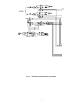
NOTES: 1. Torque set screws on blower wheel to 70 in. lb ± 2 in. lb. 2. Torque set screw on propeller fan to 15 in. lb ± 2 in. lb. 3. Dimensions are in inches. Fig. 30 — Typical Gas Heating Section Fig. 31 — Gas Heat Section Details Fig.
Evaporator Fan Coupling Assembly — If the coupling has been removed for other blower assembly component repair or replacement, it is critical that the coupling be reassembled and aligned correctly to prevent premature failures. REASSEMBLING THE COUPLING INTO THE UNIT (Fig. 33) 1. Prior to reassembling the coupling, loosen the 4 bearing mounting bolts, which secure the 2 bearings on either side of the coupling. Remove the drive belts. 2. Reassemble the coupling with the bearings loose.
CENTER DRIVE SHAFT FLEX MEMBER SHAFT FLANGE SHAFT BEARINGS Fig. 33 — Evaporator Fan Coupling Gas Valve Adjustment NATURAL GAS — The 2-stage gas valve opens and closes in response to the thermostat or limit control. When power is supplied to valve terminals 3 and 4, the pilot valve opens to the preset position. When power is supplied to terminals 1 and 2, the main valve opens to its preset position. The regular factory setting is stamped on the valve body (3.5 in. wg). To adjust regulator: 1.
Single Circuit Stoppage — If a single circuit stops REGULATOR ADJUSTMENT SCREW (REMOVE COVER) 2 LEADS, #18 WIRE 1/32 INSULATION, 600V. MAX., 105°C incorrectly, there are several possible causes. The problem should be investigated using information from the Alarm and Alert list See Table 41. OUTLET PRESSURE TAP (PLUGGED) 1/8-27 N.P.T. THDS. Service Analysis — Detailed service analysis can be found in Tables 68-70 and in Fig. 38.
Table 68 — Cooling Service Analysis PROBLEM Compressor and Fan Will Not Start. CAUSE Power failure. Fuse blown or circuit breaker tripped. Check CB1, CB2, and CB3. Disconnect off. Compressor time guard to prevent short cycling. Thermostat or occupancy schedule set point not calling for Cooling. Outdoor temperature too low. REMEDY Call power company. Replace fuse or reset circuit breaker. Power disconnect. Check using ComfortLink™ Scrolling Marquee. Check using ComfortLink Scrolling Marquee.
Table 69 — Gas Heating Service Analysis PROBLEM Burners Will Not Ignite. CAUSE Active alarm. No power to unit. No power to IGC (Integrated Gas Control). Heaters off due to time guard to prevent short cycling. Thermostat or occupancy schedule set point not calling for Cooling. No gas at main burners. Inadequate Heating. Water in gas line. Dirty air filters. Gas input too low. Thermostat or occupancy schedule set point only calling for W1. Unit undersized for load. Restricted airflow. Too much outdoor air.
IDM — IGC — LEGEND Induced-Draft Motor Integrated Gas Unit Controller NOTE: Thermostat Fan Switch in the “AUTO” position. Fig.
Table 71 — 5K Thermistor Temperature vs. Resistance (SCT Sensors) (English) TEMP (F) –25 –24 –23 –22 –21 –20 –19 –18 –17 –16 –15 –14 –13 –12 –11 –10 –9 –8 –7 –6 –5 –4 –3 –2 –1 0 1 2 3 4 5 6 7 8 9 10 11 12 13 14 15 16 17 18 19 20 21 22 23 24 25 26 27 28 29 30 31 32 33 34 35 36 37 38 39 40 41 42 43 44 45 46 47 48 49 50 51 52 53 54 55 56 57 58 VOLTAGE DROP (V) 3.699 3.689 3.679 3.668 3.658 3.647 3.636 3.624 3.613 3.601 3.588 3.576 3.563 3.550 3.536 3.523 3.509 3.494 3.480 3.465 3.450 3.434 3.418 3.402 3.
Table 72 — 5K Thermistor Temperature vs. Resistance (SCT Sensors) (SI) TEMP (C) –32 –31 –30 –29 –28 –27 –26 –25 –24 –23 –22 –21 –20 –19 –18 –17 –16 –15 –14 –13 –12 –11 –10 –9 –8 –7 –6 –5 –4 –3 –2 –1 0 1 2 3 4 5 6 7 8 9 10 11 12 13 14 VOLTAGE DROP (V) 3.705 3.687 3.668 3.649 3.629 3.608 3.586 3.563 3.539 3.514 3.489 3.462 3.434 3.406 3.376 3.345 3.313 3.281 3.247 3.212 3.177 3.140 3.103 3.065 3.025 2.985 2.945 2.903 2.860 2.817 2.774 2.730 2.685 2.639 2.593 2.547 2.500 2.454 2.407 2.360 2.312 2.265 2.217 2.
Table 73 — 10K Thermistor vs. Resistance (T55, T56, OAT, RAT, EDT, LAT Sensors) (English) TEMP (F) –25 –24 –23 –22 –21 –20 –19 –18 –17 –16 –15 –14 –13 –12 –11 –10 –9 –8 –7 –6 –5 –4 –3 –2 –1 0 1 2 3 4 5 6 7 8 9 10 11 12 13 14 15 16 17 18 19 20 21 22 23 24 25 26 27 28 29 30 31 32 33 34 35 36 37 38 39 40 41 42 43 44 45 46 47 48 49 50 51 52 53 54 55 56 57 58 59 60 VOLTAGE DROP (V) 4.758 4.750 4.741 4.733 4.724 4.715 4.705 4.696 4.686 4.676 4.665 4.655 4.644 4.633 4.621 4.609 4.597 4.585 4.572 4.560 4.546 4.
Table 74 — 10K Thermistor vs. Resistance (T55, T56, OAT, RAT, EDT, LAT Sensors) (SI) TEMP (C) –32 –31 –30 –29 –28 –27 –26 –25 –24 –23 –22 –21 –20 –19 –18 –17 –16 –15 –14 –13 –12 –11 –10 –9 –8 –7 –6 –5 –4 –3 –2 –1 0 1 2 3 4 5 6 7 8 9 10 11 12 13 14 VOLTAGE DROP (V) 4.762 4.748 4.733 4.716 4.700 4.682 4.663 4.644 4.624 4.602 4.580 4.557 4.533 4.508 4.482 4.455 4.426 4.397 4.367 4.335 4.303 4.269 4.235 4.199 4.162 4.124 4.085 4.044 4.003 3.961 3.917 3.873 3.828 3.781 3.734 3.686 3.637 3.587 3,537 3.485 3.
APPENDIX A — CCN TABLES In the following tables the structure of the tables which are used with the Service tool as well as the names and data that are included in each table are shown. As a reference the equivalent Scrolling Marquee tables and names are included. There are several CCN variables that are not displayed through the Scrolling Marquee and are used for more extensive diagnostics and system evaluations.
DESCRIPTION Status Display Status Display Status Display Status Display Status Display Status Display Status Display Status Display Status Display Status Display Status Display Status Display Status Display Status Display Status Display Status Display Status Display Status Display DESCRIPTION Status Display Status Display Status Display Status Display Status Display Status Display Status Display Status Display Status Display Status Display Status Display Status Display Status Display Status Display
OAEC_SEL OAEN_CFG ECONCPNT EDT SFAN ECONOCMD ECONOPOS OAT RETURN_T SPACE_T SENSUSED ECONHELD RAT_LOW OAT_LOCK RATSENS ECONBAND ECONRATE ECON_SEL ECONOMIN IAQMINP Status Display Status Display Status Display Status Display Status Display Status Display Status Display Status Display Status Display Status Display Status Display Status Display Status Display Status Display Status Display Status Display Status Display Status Display Status Display Status Display Status Display Status Display Status
HTSTGTYP HTCAPMAX HTOCCENA HTSGPIDR HTSGRISE HT_DGAIN HT_PGAIN HT_MR_DB HT_SG_DB Status Display Status Display Status Display Status Display Status Display Status Display Status Display Status Display Status Display Status Display Status Display Status Display Status Display Status Display Status Display Status Display Status Display Status Display Status Display Status Display Status Display Status Display CCN POINT NAME SFAN FLTS FLTSLOGC FLTS_ENA CCN POINT NAME HS1 HS1_TG HS2 HS2_TG HS3 HS3_TG
*Not used.
DESCRIPTION IAQINFAN IAQANFAN OAQANCFG OAQ_USER Configuration Configuration Configuration Configuration IAQANCFG Configuration Configuration IAQINCFG IAQOVPOS Configuration DESCRIPTION CCN POINT NAME Y1 Y2 W1 W2 G CCN POINT NAME Status Display Status Display Status Display Status Display Status Display DESCRIPTION Status Display Status Display Status Display Status Display Status Display Status Display Status Display Status Display Status Display Status Display Status Display Status
PWRM BPSELECT BPZ_GAIN BPPERIOD BPHPLVL BPLPLVL Configuration Configuration Configuration Configuration Configuration Configuration Configuration Configuration Configuration Configuration Configuration Configuration Configuration DESCRIPTION Configuration Configuration Configuration Configuration Configuration Configuration Configuration Configuration Configuration Configuration Configuration Configuration Configuration Configuration DESCRIPTION PWRX DESCRIPTION CCN POINT NAME DMDHHON DMDLHO
rmt.
Configuration Configuration Configuration Configuration Configuration Broadcast Supervisor Broadcast Supervisor Broadcast Supervisor Broadcast Supervisor Broadcast Supervisor Broadcast Supervisor Broadcast Supervisor Broadcast Supervisor Broadcast Supervisor Broadcast Supervisor Broadcast Supervisor Broadcast Supervisor Broadcast Supervisor Broadcast Supervisor Broadcast Supervisor Broadcast Supervisor Broadcast Supervisor Broadcast Supervisor Broadcast Supervisor Broadcast Supervisor Broadcast Superv
Broadcast Supervisor Broadcast Supervisor Broadcast Supervisor Broadcast Supervisor Broadcast Supervisor Broadcast Supervisor Broadcast Supervisor Broadcast Supervisor Broadcast Supervisor Broadcast Supervisor Broadcast Supervisor Broadcast Supervisor Broadcast Supervisor Broadcast Supervisor Broadcast Supervisor Broadcast Supervisor Broadcast Supervisor Broadcast Supervisor Broadcast Supervisor Broadcast Supervisor Broadcast Supervisor Broadcast Supervisor Broadcast Supervisor Broadcast Supervisor Bro
DESCRIPTION Broadcast Supervisor Broadcast Supervisor Broadcast Supervisor Broadcast Supervisor Broadcast Supervisor Broadcast Supervisor Broadcast Supervisor Broadcast Supervisor Broadcast Supervisor Broadcast Supervisor Broadcast Supervisor Broadcast Supervisor Broadcast Supervisor Broadcast Supervisor Broadcast Supervisor Broadcast Supervisor Broadcast Supervisor Broadcast Supervisor Broadcast Supervisor Broadcast Supervisor Broadcast Supervisor Broadcast Supervisor Broadcast Supervisor Broadcast S
DESCRIPTION Configuration Configuration Configuration Configuration Configuration Configuration Configuration Configuration DESCRIPTION Occupancy Supervisory Occupancy Supervisory Occupancy Supervisory Occupancy Supervisory Occupancy Supervisory Occupancy Supervisory Occupancy Supervisory Occupancy Supervisory Occupancy Supervisory Occupancy Supervisory Occupancy Supervisory Occupancy Supervisory Occupancy Supervisory Occupancy Supervisory Occupancy Supervisory Occupancy Supervisory Occupancy Superv
RTIO LIMT LSP ECONOMIN IAQMINP PE1_POS PE2_POS OACS LTMP HTMP OADEWCFG Setpoint Configuration Setpoint Configuration Setpoint Configuration Setpoint Configuration Setpoint Configuration Setpoint Configuration Setpoint Configuration Setpoint Configuration Setpoint Configuration Setpoint Configuration Setpoint Configuration Setpoint Configuration Configuration Configuration Configuration Configuration Configuration Configuration Configuration Configuration DESCRIPTION CCN POINT NAME SPKP SPKD SPKI S
CTRLTYPE SIZE VARSFAN ECON_ENA ECON_CTL ECTRMENA ECOSWCFG MAT_SEL RATSENS SPTSENS SPTOSENS SPTO_RNG SPSENS BPSENS OARHSENS RARHSENS EDTRSENS DEMLSENS FLTS_ENA DP_TRANS HPSP MM_SEL DELAY ECB1_BRD ECB2_BRD SCB_BRD EMM_BRD CCN POINT NAME SPLO SPHO SPLU SPHU SAL SAH SALU SALH RAL RAH RALU RAHU RHL RHH SPL SPH BPLO BPHI IAQL Configuration Configuration Configuration Configuration Configuration Configuration Configuration Configuration Configuration Configuration Configuration Configuration Configura
DESCRIPTION Service Configuration Service Configuration Service Configuration Service Configuration Service Configuration Service Configuration Service Configuration Service Configuration Service Configuration Service Configuration Service Configuration Service Configuration Service Configuration Service Configuration Service Configuration Service Configuration DESCRIPTION Service Configuration Service Configuration Service Configuration Service Configuration Service Configuration Service Configurat
IAQINCFG IAQOVPOS IAQANCFG Maintenance Display Maintenance Display Maintenance Display Maintenance Display IAQINFAN IAQANFAN OAQANCFG IAQREACT DAQ DAQ_LOW DAQ_HIGH DAQFNOFF DAQFNON IAQMINP ECONOMIN IAQREFL IAQREFH OAQREFL OAQREFH IAQ_MA OAQ_MA IAQ IAQMINOV OAQ IAQIN MIN_POS IAQL IAQH PURG PURGEN Maintenance Display Maintenance Display Maintenance Display Maintenance Display Maintenance Display Maintenance Display Maintenance Display Maintenance Display Maintenance Display Maintenance Disp
Maintenance Display Maintenance Display Maintenance Display Maintenance Display Maintenance Display Maintenance Display Maintenance Display Maintenance Display Maintenance Display Maintenance Display Maintenance Display Maintenance Display Maintenance Display Maintenance Display Maintenance Display Maintenance Display Maintenance Display Maintenance Display Maintenance Display Maintenance Display Maintenance Display Maintenance Display Maintenance Display DESCRIPTION Maintenance Display Maintenance D
DESCRIPTION DMD_CTRL CAP_T DMD_SW1 DMD_SW2 DLSWSP1 DLSWSP2 DMDLMTMA DMT20MA DEMLSENS DL_STAT SHED_NUM SHED_DEL SHED_TIM Maintenance Display Maintenance Display Maintenance Display Maintenance Display Maintenance Display Maintenance Display Maintenance Display Maintenance Display Maintenance Display Maintenance Display Maintenance Display Maintenance Display Maintenance Display DESCRIPTION Maintenance Display CCN POINT NAME CMPA1 CSB_A1 CSBA1ASC CSB_A1EN CMPA1LOK CMPA1STR CMPA1ENA CMPA2 CSB_A2 CS
ECON_SEL OAEC_SEL OAEN_CFG OADEWCFG SFAN ECONOCMD ECONOPOS ECONCPNT MAT_SEL MAT EDT_STAT LAT Maintenance Display Maintenance Display Maintenance Display Maintenance Display Maintenance Display Maintenance Display Maintenance Display Maintenance Display Maintenance Display Maintenance Display Maintenance Display Maintenance Display Maintenance Display Maintenance Display Maintenance Display Maintenance Display Maintenance Display Maintenance Display Maintenance Display Maintenance Display Maintena
IAQNCFG IAQANFAN IAQINCFG IAQINFAN IAQOVPOS DAQ DAQ_LOW DAQ_HIH DAQFNOFF FAQFNON IAQREACT IAQREFL IAQREFH OAQLOCK OAQANCFG IAQ_MA OAQ_MA Maintenance Display Maintenance Display Maintenance Display Maintenance Display Maintenance Display Maintenance Display Maintenance Display Maintenance Display Maintenance Display Maintenance Display Maintenance Display Maintenance Display Maintenance Display Maintenance Display Maintenance Display Maintenance Display Maintenance Display Maintenance Display
DESCRIPTION Maintenance Display Maintenance Display Maintenance Display Maintenance Display Maintenance Display Maintenance Display Maintenance Display Maintenance Display Maintenance Display Maintenance Display Maintenance Display Maintenance Display Maintenance Display Maintenance Display Maintenance Display Maintenance Display DESCRIPTION Maintenance Display Maintenance Display Maintenance Display Maintenance Display Maintenance Display Maintenance Display Maintenance Display Maintenance Display
DESCRIPTION Maintenance Display Maintenance Display Maintenance Display Maintenance Display Maintenance Display Maintenance Display Maintenance Display Maintenance Display Maintenance Display Maintenance Display Maintenance Display Maintenance Display Maintenance Display DESCRIPTION Maintenance Display Maintenance Display Maintenance Display Maintenance Display Maintenance Display Maintenance Display Maintenance Display Maintenance Display Maintenance Display Maintenance Display Maintenance Display
Maintenance Display Maintenance Display Maintenance Display Maintenance Display Maintenance Display Maintenance Display Maintenance Display Maintenance Display Maintenance Display Maintenance Display Maintenance Display Maintenance Display Maintenance Display Maintenance Display DESCRIPTION Maintenance Display Maintenance Display Maintenance Display Maintenance Display Maintenance Display Maintenance Display Maintenance Display Maintenance Display Maintenance Display Maintenance Display Maintenance D
Maintenance Display Maintenance Display Maintenance Display Maintenance Display Maintenance Display Maintenance Display Maintenance Display DESCRIPTION Maintenance Display Maintenance Display Maintenance Display Maintenance Display Maintenance Display Maintenance Display Maintenance Display Maintenance Display Maintenance Display Maintenance Display Maintenance Display Maintenance Display Maintenance Display Maintenance Display Maintenance Display Maintenance Display Maintenance Display Maintenance D
Copyright 2004 Carrier Corporation Manufacturer reserves the right to discontinue, or change at any time, specifications or designs without notice and without incurring obligations. PC 111 Catalog No. 534-80206 Printed in U.S.A.
Book 1 1 Tab 1a 1b Manufacturer reserves the right to discontinue, or change at any time, specifications or designs without notice and without incurring obligations. PC 111 Catalog No. 534-80206 Printed in U.S.A. Form 48/50A-2T Pg CL-1 1-04 Replaces: New CESR131249-CESR131227-CESR131226-CESR13174-CESR131171-- NAVI SCB CEM MARQ TECHNICIAN SUB SUBMODE — — MIN — — — X SEC IF.IS DELY MAT.S R.MAT DP.XR FAN.M SAMP — IF.M S.MM — — SEC X — — — MIN — — — — — TONS TONS SIZE S.MLV VS.
CL-2 HEAT COOL SUBMODE SUB SUBMODE — — F — — — MIN H.T.CF S.RIS S.MR.D S.DB S.P.GN S.I.GN S.DGN SEC SEC E.FOD G.FOD % — LAT.M — — OCC.H S.PI.R — N.HST S.CP.M — HT.TY — — — — — — — — — — Z.GN MIN C.TC.F A1.EN A2.EN B1.EN B2.EN A1.C.E A2.C.E B1.C.E B2.C.E SEC C.FOD — — F — — — — % MIN SEC SEC — — — — — — — — — — — — — — MIN SEC C UNITS English Metric — — F C F SETTING C.L.OA COOL HP.SP ITEM 90 0.
CL-3 ECON TMPR SUBMODE SUB SUBMODE — MIN — F — — % % UFC.T TRM.E EC.CB PWRX PWRM PE1.P PE2.P Btu/lb OEN.C UFC.C F — OA.EC OA.DL F OAT.L % % — — C — MIN — kcal/kg C — C % 35 75 4 none 2 Enabled 120 0 27 55 CURVE B 60 20 35 75 4 none 2 Enabled 120 0 27 55 CURVE B 60 20 18.0 TO 28.0 0=NONE 1=2, STAGE, 2=MODULATING 1=4 MOTORS, 2=6 MOTORS 0 TO 100 0 TO 100 0.5 TO 5.
CL-4 IAQ BP SVFD SUBMODE SUB SUBMODE in-H2O — — SP.H.L SP.L.L BP.SL BP.S % — IA.I.C MIN.I — IA.FN % — IA.CF AQ.MP in-H2O BP.LP — in-H2O BP.HP IA.I.F — MIN BP.ZG BP.DT in-H2O in-H2O SP.KI SP.K SP.DT BP.R — — — sec SP.KD — SP.KP % % SF.MX SF.FS % % — — — — cm-H2O cm-H2O — cm-H2O — — cm-H2O cm-H2O — — sec — — % % 20 0 0 0 0 0 0.04 0.05 1 1 0.25 2 DSBL 0 5 2 1 2 0 20 100 100 20 % SF.MN % none — 20 0 0 0 0 0 0.04 0.05 1 1 0.
CL-5 OPTS IAQ (cont) SUBMODE SUB SUBMODE ppm ppm ppm ppm ppm ppm ppm — — — — — F — — — — I.20M O.4M O.20M I.CRV OPTS EDT.R ECO.S FLS.E SPT.S STO.S STO.R R.RH.S O.RH.S DMT.S RMT.C — — — — — — C — — — ppm ppm ppm ppm ppm I.4M ppm ppm ppm ppm AQD.L ppm ppm ppm OAQ.L — DF.OF — OAQ.U — DF.ON — OA.CF % ppm % OVR.P MIN % % AQD.H MIN % % PRG.D PG.LT PG.HT — UNITS English Metric — SETTING PRG.
CL-6 CCN DMD.L RST CMF.D SUBMODE SUB SUBMODE — F — % — % MIN % % — — RTIO R.LIM DMD.L DMLS D.L.20 LS.GN LS.DD LS.TM DLS.1 DLS.2 CCN CCN.A CCN.B B.TIM B.OAT B.ORH B.OAQ B.GS B.ACK — — % % MIN % — % — — C — C C C sec C sec — — — — — — — — — — — — BITS/SEC BITS/SEC — RST.T BAUD F F F sec F sec LH.OF HH.ON CT.LV CT.TM HT.LV HT.TM RST C C C C UNITS English Metric F F F F SETTING LC.ON LC.OF HC.ON LH.
CL-7 SW.LG DISP SUBMODE SUB SUBMODE — — — PSWD OPEN OPEN OPEN OPEN PRS.L PRG.L PMI.L SFS.L OPEN FTS.L IAQ.L OPEN OPEN EVC.L OPEN OPEN EC.SL FSD.L OPEN DM.2.L OFF 1111 ENBL OPEN — ENGLISH OFF OPEN OPEN OPEN OPEN OPEN OPEN OPEN OPEN OPEN OPEN OPEN OFF 1111 ENBL ENGLISH OFF FACTORY DEFAULT VAV CV DM.1.L SW.
CL-8 ALLM SUBMODE SUB SUBMODE F % % H2O H2O H2O H2O ppm IRH.H DP.L DP.H BP.L BP.H IQ.HI F RAL.U IRH.L F RAH.O RAH.U F F SAH.U RAL.O F SAL.U C F F SAL.O F SPH.U SAH.O C F SPL.U % pa pa pa pa ppm % C C C C C C C C C F SPH.O C UNITS English Metric F SETTING ALLM SPL.O ITEM 100 0 2 -0.25 0.25 800 0 120.0 35.0 90.0 60.0 180.0 45.0 180.0 45.0 100.0 45.0 80.0 65.0 100 0 2 -0.25 0.25 800 0 120.0 35.0 90.0 60.0 180.0 45.0 180.0 45.0 100.0 45.
UNIT START-UP CHECKLIST MODEL NO.: _________________________________ SERIAL NO.