
User's Manual

ALPHA meter
IL42-4001S
3
After you install a bottom-connected meter, check the following:
• If load is applied, check that the pulse arrows on the LCD are blinking.
The LCD has 2 sets of pulse arrows, one located above the other. The upper set of arrows indicates
watthours, and the lower set indicates alternate energy (kVARh or kVAh, if available). The arrows
pointing to the left indicate energy received; arrows pointing to the right indicate energy delivered.
For more information, see the technical manual for your meter.
• The TEST annunciator is not blinking. If it is blinking, then remove the meter from service, remove the
cover, and rotate the TEST button so that the meter is placed out of test mode. For more information,
see the technical manual for your meter.
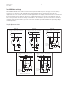
Forms 45S, 45A, and 56S safety precautions
Form 45S, Form 45A, and Form 56S meters present additional risks of electrical shock that may result
in severe personal injury or death when the cover is removed from energized meters unless certain
additional safety procedures and precautions are followed. Be sure to follow the safety procedures
and precautions when servicing Form 45S, Form 45A, and Form 56S meters as stated in this manual
as well as your authorized procedures.
When using Forms 45S, 45A, and 56S meters, be sure to understand and follow the important safety-
related concerns.
• Form 45S meters: safety concerns exist with Form 45S meters in any application in which socket jaw
7 is not grounded.
• Form 45A meters: safety concerns exist with Form 45A meters in any application in which the
equivalent terminal to the Form 45S socket jaw 7 is not grounded (A-base voltage terminal #6, as
numbered from left-to-right).
• Form 56S meters: safety concerns exist with Form 56S meters in any application in which socket jaw
16 is not grounded.
These safety concerns include, but are not necessarily limited to, the following:
• 3-wire delta applications
• dual single phase “star” configurations (may also be referred to as 5-wire, 2-phase)
• 4-wire delta applications in which the high leg is not tied to phase C
The primary safety concerns in these applications are as follows:
1 The meter battery terminals and circuit board electronics will be at line potential.
2 The circuit board electronics of any installed option board will be at line potential.
3 Any internal antenna or other electrical extension of any installed option board will be at line
potential.
It is important to assess the potential hazards after removing the meter cover and disconnect the
electrical power as necessary to perform service.