
User's Manual

A3 ALPHA meter with wireless 3G cellular communications 2
Use authorized utility procedures to install and service metering equipment. Dangerous voltages are
present. Equipment damage, personal injury, or death can result if safety precautions are not
followed.
Use circuit closing devices on current transformer secondaries (3S, 4S, 5S, 5A, 6S, 6A, 8S, 9S, 10S, 10A,
26S, 29S, 35S, 36S, and 36A meters). Equipment damage, personal injur y, or death can result if circuit
closing secondaries are not used.
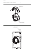
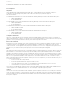
Location of antennas
See Figure 1 for the location of the Wireless WIC internal antenna.
The Wireless WIC internal antenna is fix-mounted to the periphery of the A3 ALPHA meter’s electronic
housing. The Wireless WIC antenna is not adjustable or removable.
Alternatively, A3 ALPHA meters may be ordered with an external WIC antenna. With this option, the
meter is shipped with an RF “pigtail” output cable which allows connection to a multi-band cellular
antenna external to the meter. This is advantageous in locations with lower cellular signal strength.
Also, certain Wireless WIC configurations (for example, UMTS/HSPA+) are presently only available with
an external WIC antenna.
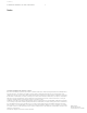
See Figure 2 for the recommended location of the Wireless WIC external antenna. Elster recommends
mounting the external Wireless WIC cellular antenna on the top of the meter socket box as shown,
centered in the available space on the meter box’s top surface.
• Drill and/or punch the specified antenna mounting hole in the top of the meter socket box and install
the antenna using the antenna manufacturer’s instructions.
• Connect the meter's RF “pigtail” output cable directly to the antenna via its integral N-type connector.
The Wireless WIC antenna output cable may be ordered in two lengths: 19 or 36 inches. Choose the
length based on the distance from the meter to the Wireless WIC external antenna, which is in turn
determined by the size of the meter socket box.
Please note that external cellular antennas must be purchased separately, either from Elster or a third
party, from a list of approved antennas. Please ask your Elster Sales Representative for the current list
of approved external cellular antennas.
Use approved utility safety procedures while installing the external antenna and meter RF output
cable in the meter socket box. Dangerous voltages may be present. Assure that there is sufficient
clearance between any line-energized socket part and the exposed metal of the antenna connectors.
Also assure that the external antenna is electrically bonded to the meter socket box. Failing to follow
approved utility safety procedures, failing to allow sufficient clearance, or failing to electrically bond
the external antenna to the meter socket box may result in equipment damage, personal injury, or
death.
Preliminary