
User's Manual

CHAPTER 6 VRT REMOTE GAS-METER TRANSPONDER INSTALLATION
VRT Gas Transponder ― User Guide Page 27
AMCO Automated Systems
•
P/N 52870T010 Rev 1 May 2003
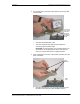
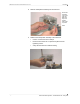
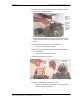
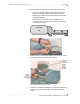
6. Slip one of the short spacers over the portion of each post
protruding above the pulser board.
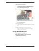
7. Route the pulser wires toward the notch cut earlier in the index
box.
• Be sure the wires are not pinched under either the posts or
the spacers.
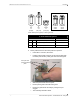
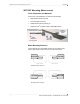
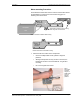
Put short spacers
on protruding
portion of posts
Pulser board
(front)
Faces toward
index, gears
en
g
a
g
ed
INDEX (back)
INDEX (front)
Pulser board
(back)
Index post
Index post