
Installation Instructions


Water 4.0 module
Installation instructions
IL42-5050B
GENERAL
This leaflet contains instructions for the Honeywell Water 4.0 module for use on water meters to provide readings to the
EnergyAxis® and SynergyNet systems. For proper installation and maximum life of the modules, use the following procedures.
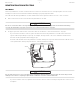
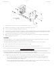
The Honeywell Water 4.0 module can be installed as a wall or pipe mount. Honeywell also provides a pit mount version of the
Water 4.0 module. The wall mount is mounted to a mostly flat surface such as a wall or other surface. See “Wall mount” on
page 2 for specific instructions. The pipe mount consists of hardware to mount the module to a pipe. See “Pipe mount” on
page 3 for specific instructions.
Familiarize yourself with the location and identification of the terminals on your water meter registers before any installation
procedure.
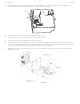
RADIO COMMUNICATIONS PERFORMANCE & MOUNTING
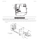
The Honeywell Water 4.0 module is designed to provide excellent radio communications performance when it is mounted such
that the front surface arrows point up. Alternate mounting orientations may impair radio communications performance.
All Water modules are shipped with their radio in a deep sleep mode. To activate the radio and program the register interface,
use Honeywell’s Installer software.
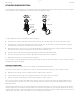
CONNECTION INSTRUCTIONS
The Honeywell Water 4.0 module register connections are as follows:
For pulse (incremental) encoders, use the following register connections:
Function Module cable color Register terminal color
Honeywell Badger Sensus Mueller Neptune
Data Green Green Green Green Green Red
Power (or power/clock) Red Red Red Red Red Black
Common (ground) Black Black Black Black Black Green
Function Module cable color Badger
(3-wire)
Badger
(2-wire)
Honeywell
AMCO digital
Common (ground) Black Black Black Red
Pulse output Green Red Red Black
Tamper Red Green/Bare — Green
Preliminary