Certification Exhibit FCC ID: QZC-REXU IC: 4557A-REXU FCC Rule Part: 15.247 IC Radio Standards Specification: RSS-247 ACS Project Number: 15-0255 Manufacturer: Elster Solutions, LLC Model: REXU 5015 B.U.
:55 pm, Sep 11, 2015 REX® meter family Installation instructions IL42-4026J General This leaflet contains installation instructions for the solid-state, residential electricity meters in the REX family (referred to as “REX” within this IL) with the following form factors: • self-contained: Forms 1S, 2S, and 12S • transformer-rated: Forms 3S and 4S All meters are calibrated and sealed before shipment. For proper installation, accuracy, and maximum life of the meters, use the following procedures.
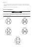
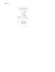
REX® meter family IL42-4026J 2 6 The LCD has two pulse arrows. The arrow pointing to the left indicates energy received; the arrow pointing to the right indicates energy delivered. For more information, see the technical manual for your meter. 7 Apply all seals and record any necessary information. Internal wiring diagrams Circuit closing devices must be used on current transformer secondaries. This applies to Form 3S and 4S meters.
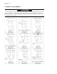
REX® meter family IL42-4026J 3 Installation wiring diagrams Circuit closing devices must be used on current transformer secondaries. This applies to Forms 3S and 4S meters. Dangerous voltages are present if current transformer secondaries are open-circuited while the transformer is energized. Equipment damage, personal injury, or death can result if circuitclosing devices are not used.
REX® meter family IL42-4026J 4
REX® meter family IL42-4026J 5 FCC and Industry Canada Compliance The radio module is manufactured directly onto the meter main circuit board, and the module is inserted into the electronic housing of the meter at manufacture. It has no user serviceable parts. For the most current REXUniversal meter compliance information, see PG42-1060. User Information (Part 15.105): This equipment has been tested and found to comply with the limits for a Class B digital device, pursuant to part 15 of the FCC Rules.
REX® meter family IL42-4026J 6 Notes: DISCLAIMER OF WARRANTIES AND LIMITATIONS OF LIABILITY There are no understandings, agreements, representations, or warranties either express or implied, including warranties of merchantability or fitness for a particular purpose, other than those specifically set out by any existing contract between the parties. Any such contract states the entire obligation of the seller.
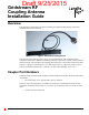
Draft 9/25/2015 Gridstream RF Coupling Antenna Installation Guide Publication: 98-1245 Rev AF LANDIS+GYR CONFIDENTIAL INFORMATION
Draft 9/25/2015 Limitation on Warranties and Liability Information in this document is subject to change without notice. This manual or any part of it thereof may not be reproduced in any form unless permitted by contract or by written permission of Landis+Gyr.
Draft 9/25/2015 Gridstream RF Coupling Antenna Installation Guide Overview This publication outlines the procedure for installing the Gridstream RF Coupling Antenna on Gridstream RF Electric Endpoints. Figure 1. Gridstream RF Coupling Antenna This antenna couples radio frequency energy to an external antenna. This is useful for meter installations where there is difficulty in obtaining adequate reception. For example, meters located in metal enclosures or in a basement.
Draft 9/25/2015 Gridstream RF Coupling Antenna Installation Guide Landis+Gyr Required Materials The following materials are required to complete a RF Coupling Antenna installation.
Draft 9/25/2015 Landis+Gyr Gridstream RF Coupling Antenna Installation Guide Performance Table 1. Performance Parameter Minimum Frequency 902 Typical Maximum Units 928 MHz 9 dB Coupling Loss 5 Polarization Linear VSWR 1.78:1 Impedance 50 ohm Input RL 11 dB Condition Final antenna assembly on FOCUS AX: modular Final antenna assembly on FOCUS AX: modular Qualified Meters The following table provides a list of qualified module and meters. Table 2.
Draft 9/25/2015 Gridstream RF Coupling Antenna Installation Guide Landis+Gyr General Installation Guidelines Determine the optimum location for Gridstream Remote antenna installation. This will vary depending on the location of the meter. In general, the antenna should be: • Installed as close to line of sight with a Gridstream RF network equipment as is possible. • Mounted so that it is at least four inches from the nearest structure.
Landis+Gyr Draft 9/25/2015 Gridstream RF Coupling Antenna Installation Guide Gridstream RF Enhanced FOCUS AX/AX-SD Mounting Procedure This procedure supports the L+G FOCUS AX meter. NOTE: The RF Coupling Antenna should be mounted within 5 mm (0.25") of the indicated location to achieve specified performance. 1. Clean the meter cover where the flex antenna will be installed. Wipe the cover mounting area with an alcohol wipe and let the area dry for one minute before proceeding with the installation.
Draft 9/25/2015 Gridstream RF Coupling Antenna Installation Guide Landis+Gyr Gridstream RF Enhanced S4e Mounting Procedure This procedure supports the L+G AXS4e, L+G RXS4e, L+G AXRS4e, and L+G RXRS4e meters. NOTE: The RF Coupling Antenna should be mounted within 5 mm (0.25") of the indicated location to achieve specified performance. 1. Clean the meter cover where the flex antenna will be installed.
Draft 9/25/2015 Landis+Gyr Gridstream RF Coupling Antenna Installation Guide 8 Secure the cable to the side of the structure using appropriate hardware for the building construction. See Figure 5. Align the antenna center point on the meter housing at the 2:30 o’clock position, 1.5 cm clockwise past the nub on the outer meter cover Figure 5.
Draft 9/25/2015 Gridstream RF Coupling Antenna Installation Guide Landis+Gyr Gridstream RF Enhanced Integrated FOCUS AX/AX-SD Mounting Procedure This procedure supports the L+G FOCUS AX, L+G FOCUS RXAX, L+G FOCUS AXR, and L+G FOCUS RXR meters. NOTE: The RF Coupling Antenna should be mounted within 5 mm (0.25") of the indicated location to achieve specified performance. 1. Clean the meter cover where the flex antenna will be installed.
Landis+Gyr Draft 9/25/2015 Gridstream RF Coupling Antenna Installation Guide 7. Once installed to the antenna, wrap the connector using cold flow tape. Tape should be wrapped tightly and in a continuous manner. The tape should cover the cable one inch past the end of the connector. 8. Secure the cable to the side of the structure using appropriate hardware for the building construction.
Draft 9/25/2015 Gridstream RF Coupling Antenna Installation Guide Landis+Gyr Gridstream RF Enhanced Elster A3 Mounting Procedure This procedure supports the L+G Elster A3RALNQ meter. NOTE: The passive antenna should be mounted within 5 mm (0.25") of the indicated location to achieve specified performance. 1. Clean the meter cover where the flex antenna will be installed. Wipe the cover area with an alcohol wipe and let the area dry one minute before proceeding with the installation. 2.
Landis+Gyr Draft 9/25/2015 Gridstream RF Coupling Antenna Installation Guide 5. Ensure that the cable tie is evenly placed over the antenna and cinch tight. 6. Install the remote antenna at the location indicated by the link assessment performed. If a link assessment tool is not available, select a location that provides the best line of sight to the nearest collector. 7. Once installed to antenna, wrap the connector using cold flow tape.
Draft 9/25/2015 Gridstream RF Coupling Antenna Installation Guide Landis+Gyr Gridstream RF Enhanced Elster REXU Mounting Procedure This procedure supports the TBD meter. NOTE: The passive antenna should be mounted within 5 mm (0.25") of the indicated location to achieve specified performance. 1. Clean the meter cover where the flex antenna will be installed. Wipe the cover area with an alcohol wipe and let the area dry one minute before proceeding with the installation. 2.
Landis+Gyr Draft 9/25/2015 Gridstream RF Coupling Antenna Installation Guide 7. Once installed to antenna, wrap the connector using cold flow tape. Tape should be wrapped tightly around the cable and in a continuous manner. The tape should cover the cable one inch past the end of the connector. 8. Secure the cable to the side of the structure using appropriate hardware for the building.
Draft 9/25/2015 Gridstream RF Coupling Antenna Installation Guide Landis+Gyr Gridstream RF Enhanced S4x Mounting Procedure This procedure supports the L+G E650 RXRS4X meter. NOTE: The RF Coupling Antenna should be mounted within 5 mm (0.25") of the indicated location to achieve specified performance. 1. Clean the meter cover where the flex antenna will be installed. Wipe the cover area with an alcohol wipe and let the area dry one minute before proceeding with the installation. 2.
Landis+Gyr Draft 9/25/2015 Gridstream RF Coupling Antenna Installation Guide 8. Secure the cable to the side of the structure using appropriate hardware for the building. Align the antenna center point on the meter housing at the 5:30 o’clock position, 6.5 cm clockwise below the top surface of the meter cover Figure 13.
Draft 9/25/2015 Gridstream RF Coupling Antenna Installation Guide Landis+Gyr Antenna Brackets and Antenna Mounting Figure 14. Typical Remote Antenna Brackets 18 NOTE: To mount these brackets, use screw and bolt hardware that is approved by the local utility.
Landis+Gyr Draft 9/25/2015 Gridstream RF Coupling Antenna Installation Guide Figure 15.