
User's Manual

Chapter 3 Controls & Indicators
Transmitter/Receiver Status Indicators:
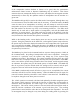
The MMI is equipped with eight receivers and one transmitter. All of these devices use
phase-locked-loops (PLL’s) to control each frequency with a high degree of accuracy.
The PLL’s also allow both transmitter and receiver frequencies to be easily changed with
software in real time. Many of the status LED’s to be described below display PLL
programming status. Since each PLL is software programmable, it is important to be able
to instantly verify if a particular one has been programmed correctly. It is possible to
improperly, either intentionally or accidentally, program a PLL to a frequency where the
transmitter or receiver is not able to operate correctly. In this case, the PLL OK LED
would be turned off.
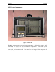
There are four receiver boards with two receivers on each board. These cards and their
locations are displayed in figure 3. Each receiver channel has two LED’s to display
programming and data status. Each green LED on the receiver boards is used to verify
that particular channel has been programmed to a valid frequency. The green LED’s
should be illuminated at all times during operation except for approximately 7 seconds
after MMI power is initially applied. During this time, the LED’s may be either on or off
randomly. During normal operation, all green LED’s should be illuminated. The red
LED’s will flash any time a particular channel is receiving valid data, visually verifying
that the receiver is working properly.
There is one transmitter board in the MMI and its location is shown in figure 3. The
transmitter has three LED’s used to display its status. The Power OK LED should be
illuminated any time the MMI is powered. As with the receiver PLL OK LED, the
transmitter PLL OK LED should be illuminated at all times. The TX On LED displays
whether the transmitter has been enabled by the software. Referring to figure 2, anytime
the TX On LED is illuminated, the RF Amp Enabled LED should be illuminated as well.
This verifies that the RF amplifier is operating.
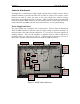
Figure 3.
Transmitter/
Receiver Status
Indicators
Receiver Cards
#1&2 #3&4 #5&6 #7&8
Transmitter
Card
PLL OK
Data
PLL OK
Data
Power OK
PLL OK
N
ot used
TX On
CH1 CH3 CH5 CH7
CH2 CH4 CH6 CH8