
User's Manual

Chapter 3 Controls & Indicators
Controls & Indicators
The MMI uses a combination of LED’s (light emitting diodes), audible alarms, and the
handheld terminal to provide both status and a means of control to the operator. These
indicators are used to convey the status of the power supply unit, external voltages,
temperature, and transmitter/receiver operation. This section should be well understood
before operating the MMI. Failure to become familiar with the various status and control
features built into the MMI could lead to poor performance, or even system damage.
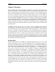
Power Supply Indicators:
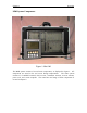
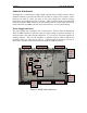
The power supply unit is equipped with 3 status LED’s. Each of these are illuminated
when the MMI is powered, and each respective supply voltage is operation normally. As
shown in figure 2, the LED’s denote whether the +5, +12, and -12 volt power supplies are
working properly. Also, the RF amplifier is equipped with an LED to indicate the
condition of the +12 volts used to power it. Under normal circumstances, all four of
these LED’s should be illuminated at all times while the MMI is powered.
Figure 2. MMI Status Indicators
+5 volts O
K
+12 volts O
K
-12 volts O
K
RF
AMP
Power
O
K
RF AmplifierPower SupplyPower /
Status
Pane
l
+12
Batt
Tem
p
AlarmAlarm
Silence
Switch
Main
Power
Switch
RF
AMP
Enabled