
User's Manual

455U Radio Modem Module User Manual
Page 46 © November 2004
6.2 Test Functions
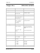
6.2.1 Radio Testing - AT&Tx
To aid in the checking and setup of the 455U unit, diagnostic functions are provided using the
standard Hayes AT commands. To perform the tests, you will need a terminal (PC + hyper-
terminal) set-up to match the module (same character type and serial speed). The table below
outlines the functions of the various tests:
AT&T Radio Self Tests. Allows in-field diagnostics, and factory testing.
&T0 Stop Tone Reversals.
&T1 Tone Reversals – 200 HZ modulation
&T2 Tone Reversals – 2400 HZ modulation
&T3 Tone Reversals – No modulation
&T4 Random Tone Reversals. Generates pseudo random data and sends out radio.
&T5 RSSI Measurement. Monitors the received signal strength, and displays in dBm
Most radio tests are carried out using the AT&T2 test as this is the easiest to accomplish.
AT&T5 - Received Signal Strength Display
This option provides for testing the radio path between two 455U units. Although a pair of
units may communicate successfully, radio communication may be affected by a range of
influences, including atmospheric conditions, changing landscape, degradation of antennas or
co-axial cable, low battery voltage etc. Fade margin is an indication of how far a radio path
can deteriorate before reliable communication becomes unreliable.
When using this feature, the current value of the received signal strength is displayed in dBm
(decibels referenced to 1 mW). This value is updated every half second. To check the radio
path between two units, force the remote unit to generate data and read the signal level from
the local terminal. The remote unit can be forced to transmit by selecting AT&T2.
Also measure the background noise by stopping transmission from the remote module and
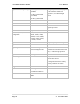
reading the value from the terminal. For reliable operation (that is, a bit error rate of more
than 1 in 300) the transmitted signal should be better than the following margins:
Radio Baud Rate Margin above Noise Minimum Value (dBm)
9600 10 -95
4800 10 -105
When using directional antennas (YAGI antennas) this feature may be used to align the
antenna in the correct direction by selecting the peak signal when moving the antenna. Setup
the remote unit to transmit, and observe the signal indication while adjusting the orientation
of the antenna. A peak in signal level indicates optimum orientation of the antenna.