
User's Manual

Chapter Three Operation
Man_455U Rev 1.0 Page 21
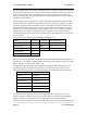
The time for each byte is 1.04msec @9600 bits/sec, 2.08 mSec ant 4800 baud, and 4.16
mSec at 2400 baud.. If error checking is not configured at the receiving unit, data will start
to be output approx 1msec after the first data byte has been received. If error checking is
configured, data will be output approx 2msec after the end of the message. For example, a
message with 20 bytes of data transmitted at 9600 bits/sec with no repeaters, will be output
approx 52msec after the data is input, if error checking is configured, and will be output
approx 29 mSec after the data is input if no error checking is configured. Error checking is
configured with the AT&E command, Data Encryption is configured with the AT#E and
AT#S commands.
A “transmit delay” time and a “receive delay” time may also be configured. These parameters
may be used to fine tune and give priority to different 455U units in a system.
• After each message is transmitted, a 455U unit will not transmit another message during the
transmit delay time. This could be used to allow a reply message to be received before the
next message is sent.
• After a message is received, a message will not be transmitted during the receive delay time.
This could be used to delay a reply message until other messages have been sent.
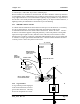
3.3 Addressing
A 455U network comprises modules with the same "system" address. Only modules with the
same system address will communicate with each other. This feature allows more than one
system to operate in the same area on the same radio channel.
A 455U must also be configured with a “unit” address - this gives the module a unique
identification. The Unit address is used when issuing a “Dial” command to the modem (ATD)
and when configuring the RS232 path, The RS485 path and the Stored Numbers (AT&Z)
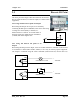
Each 455U has two addresses, the RS232 port is accessed by addressing the configured unit
address. The RS485 port is accessed by addressing the configured unit address +128. So, to
access the RS232 port on unit 7, use address 7. To access the RS485 port on this unit, use
address 135 (128+7).
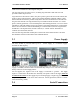
Addresses 0 and 128 are reserved as “wildcard” addresses. Sending a message to address 0
results in all modules accepting the message. Address 0 refers to every RS232 port in the
system. Address 128 is the wildcard address for every RS485 port in the system.
Every modem can also act as a repeater unit for other modems in the system. If the modem
is expected to repeat messages to the wildcard address, the repeater mode should be set to
“wild card” (AT&R1)
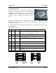
3.4 Unacknowledged Mode
In unacknowledged mode, units do not provide handshaking functions to control the flow of
data. Messages are not acknowledged, and are sent on a “Best attempt” basis. It is up to the
host equipment to determine if data is lost or corrupted.