
User's Manual

455U Radio Modem Module User Manual
Page 16 © November 2004
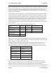
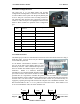
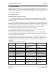
2.4.2 RS232 Configuration Port
The serial port is a 9 pin DB9 female and provides
configuration and diagnostics of both the local module and
of other modules in the system wile the primary RS232 port
is active. This port is wired as a DCE according to EIA-561.
The following table describes the connections required to
connect to a PC serial port. The highlighted entries in this
table are those essential for operation of the Configuration
port.
RJ-45
Pin
E455U Modem
Function
EIA-561 Signal Name
1 None Ring Indicator
2 None Data Carrier Detect
3 Input Data Terminal Ready
4 Common Signal Common
5 Output Receive Data (from Modem)
6 Input Transmit Data (to Modem)
7 None Clear to Send
8 None Request to Send
2.4.3 RS485 Serial Port
The RS485 port provides for communication between the 455U unit and its host device using a
multi-drop cable. Up to 32 devices may be connected
in each multi-drop network.
As the RS485 communication medium is shared,
only one of the units on the RS485 cable may send
data at any one time. Thus communication protocols
based on the RS-485 standard require some type of
arbitration. RS485 is a balanced, differential
standard but it is recommended that shielded, twisted
pair cable be used to interconnect modules to reduce
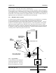
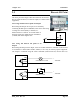
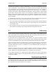
potential RFI. It is important to maintain the polarity of the two RS485 wires. An RS485
network should be wired as indicated in the diagram below and terminated at each end of the
network with a 120 ohm resistor. On-board 120 ohm resistors are provided and may be
engaged by operating the single DIP switch in the end plate next to the RS485 terminals. The
DIP switch should be in the “1” or “on” position to connect the resistor. If the module is not
at one end of the RS485 cable, the switch should be off.
HOST
455U
HOST
RS485 CONNECTIONS