
User's Manual

Chapter Two Installation
Man_455U Rev 1.0 Page 15
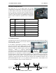
2.4.1 RS232 Serial Port
The serial port is a 9 pin DB9 female and provides for
connection to a host device as well as a PC terminal for
configuration, field testing and for factory testing.
Communication is via standard RS232 signals. The 455U is
configured as DCE equipment with the pinout detailed
below.
Hardware handshaking using the CTS/RTS lines is provided. The CTS/RTS lines can be
configured to reflect the status of the local unit’s input buffer. The 455U supports
XON/XOFF flow control.
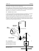
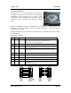
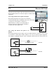
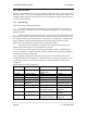
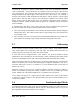
Example cable drawings for connection to a DTE host (a PC) or another DCE host (or modem)
are detailed below.
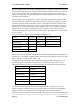
DB9 Connector Pinout
Pin Name Direction Function
1 DCD Out
Data carrier detect –
- driven when link is established in Acknowledged mode
- driven always in unacknowledged mode
2 RD Out
Transmit Data from modem – Serial Data Output
3 TD In
Receive Data into modem – Serial Data Input
4 DTR In
Data Terminal Ready - DTR can be configured to initiate low power
mode, or to force a link disconnection (“hang up” in Acknowledged
mode.
5 SG
Signal Ground
6 DSR Out
Data Set Ready - always high when unit is powered on.
7 RTS In
Request to Send - hardware flow control configurable
8 CTS Out
Clear to send - hardware flow control configurable
9 RI Out
Ring indicator - indicates another module is attempting to connect in
Acknowledged mode.
455U
DB9
MALE
DTE HOST
DB9
FEMALE
455U
DB9
MALE
DCE HOST
DB9
MALE