
User's Manual

455U Radio Modem Module User Manual
Page 14 © November 2004
cable loss for installations with marginal radio path.
The Yagi gain also acts on the receiver, so adding Yagi antennas at both ends of a link
provides a double improvement.
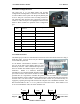
Yagi antennas are directional. That is, they have positive gain to the front of the antenna, but
negative gain in other directions. Hence Yagi antennas should be installed with the central
beam horizontal and must be pointed exactly in the direction of transmission to benefit from
the gain of the antenna. The Yagi antennas may be installed with the elements in a vertical
plane (vertically polarized) or in a horizontal plane (horizontally polarized). For a two station
installation, with both modules using Yagi antennas, horizontal polarization is recommended.
If there are more than two stations transmitting to a common station, then the Yagi antennas
should have vertical polarization, and the common (or “central” station should have a
collinear (non-directional) antenna.
Also note that Yagi antennas normally have a drain hole on the folded element - the drain
hole should be located on the bottom of the installed antenna.
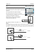
2.3 Power Supply
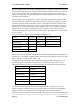
The 455U module is powered either by an 12 - 15VDC supply, or a 18-28VDC supply.
minmum 24 Watt capacity.
The 12-15 V Supply may be used to charge a backup battery (12V Lead-acid) when the main
supply is available, and the module will automatically change over to run from the backup
battery in the case of main supply failure.
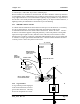
For DC supplies, the negative side of the supply is connected to “ground”. The supply
negative is connected to the module case internally. The positive side of the supply must not
be connected to earth. The DC supply may be a floating supply or negatively grounded.
The power requirements of the 455U units is 90mA at 12VDC (Quiescent) and 2A at 12VDC
when transmitting (5Watt).
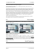
2.4 Serial Connections