
User's Manual

455U Radio Modem Module User Manual
Page 12 © November 2004
effect than obstructions in the middle of the radio path. For example, a group of trees around
the antenna is a large obstruction, and the antenna should be raised above the trees. However
if there is at least 100 metres of clear path before a group of trees, the trees will have less
affect on the radio path. To help in planning radio systems, ELPRO provides a free utility for
estimating path performance.
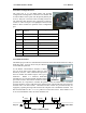
The modules provide test diagnostics to test the radio path and display radio signal strength.
An antenna should be connected to the module via 50 ohm coaxial cable (eg RG58, Cellfoil
or RG213) terminated with a male SMA connector. The higher the antenna is mounted, the
greater the transmission range will be, however as the length of coaxial cable increases so do
cable losses. For use on unlicensed frequency channels, there are several types of antennas
suitable for use. It is important antennas are chosen carefully to avoid contravening the
maximum allowed power limit on the on the radio channel - if in doubt refer to an authorized
service provider.
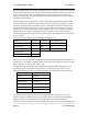
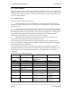
The gains and losses of some typical antennas and cable types are
Cable type Loss (dB per 10 m)
RG58 -4.5
RG213 -1.65
Cellfoil -2.25
The net gain of the antenna/cable configuration is determined by adding the antenna gain and
the cable loss. For example, a 6dBd Collinear with 20 metres of RG58 has a net loss of 1 dB
(8dB – ((20/10) x 4.5) dB) = 8dB – 9dB = -1dB
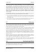
Another important consideration when installing the antenna system is RF exposure. The
antenna can radiate a large amount of RF energy. It is important to ensure that a person
approach the antennas within the recommended minimum safe distances in the table below.
Antenna Type Minimum safe distance
Dipole 0.4 metres
3dBd Collinear 0.7 metres
6dBd Collinear 0.9 metres
6 element Yagi 1.2 metres
9 element Yagi 1.5 metres
16 element Yagi 2.3 metres
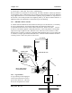
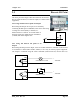
Connections between the antenna and coaxial cable should be carefully taped to prevent
ingress of moisture. Moisture ingress in the coaxial cable is a common cause for problems
with radio systems, as it greatly increases the radio losses. We recommend that the
connection be taped with a layer of PVC insulating tape, then a layer of vulcanizing tape such
Antenna Gain (dB)
3dBd Collinear 5
6dBd Collinear 8
6 element Yagi 9
9 element Yagi 12
16 element Yagi 15